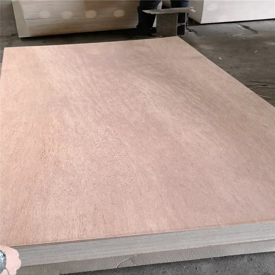
Warm wood faces. Components that fit your assembly.
Make furniture inserts, drawer components and divider kits with the Bintangor face and finished fit your assembly needs. Choose calibrated 6mm plywood as full sheets, cut blanks or machined parts. Send a component photo, frame detail or compartment layout; our factory team can help develop the core, slot fit, finish and packing around your order.
Available to order · 10–15 days production · Container shipping
TECHNICAL DATA · TDS-PS-01 · Rev 2.0 (Oct 2026)
6mm Bintangor Plywood technical data
Our 6mm Bintangor-faced plywood brings a warm wood surface to furniture components and interior work. Choose the face/reverse pairing, core and finished size together. At the transport-table planning density of 550 kg/m³, a 1220 × 2440 × 6 mm sheet weighs about 9.8 kg; the selected core determines the shipment weight.
Declared values from our technical data sheet TDS-PS-01, Rev 2.0 (Oct 2026). The values for your order are confirmed in the quotation.
Harmonized System (HS) Code
4412.33 / 4412.39
Reference Standards
EN 636-1 / EN 636-2, EN 314-2 (Class 1 / Class 2), EN 13986, ANSI/HPVA HP-1, GB/T 9846
Intended exposure / EN 636 class
Dry interior (EN 636-1) or humid interior (EN 636-2)
Decorative Face / Reverse
Bintangor decorative face (0.30–0.65 mm); Bintangor reverse or another reverse material specified with the face/back pair
Cross-grained rotary-cut veneers, two-time hot pressing and calibration; veneer thickness and ply arrangement selected for the finished panel
Adhesive System
Urea-formaldehyde (UF) or melamine-urea-formaldehyde (MUF), with the required emissions formulation specified for the order
Surface Finishing
Double-sided belt calibrated and fine sanded (120#–180# grit)
Standard Sheet Sizes
1220 × 2440 mm (4' × 8'), 1250 × 2500 mm, 915 × 2135 mm (Door size)
Length & Width Tolerance
±1.0 mm (EN 315)
Thickness Tolerance (Calibrated Sanded)
≤ 6 mm: ±0.2 mm | 9–15 mm: ±0.3 mm | ≥ 18 mm: ±0.4 mm (EN 315)
Squareness (Diagonal Difference)
≤ 1.0 mm / m (Max 2.0 mm per 1220×2440 sheet) (EN 324-2)
Edge Straightness Tolerance
≤ 1.0 mm / m (EN 324-2)
Panel Flatness / Bow / Warp
18 mm series reference: ≤ 3.0 mm / m (EN 315). For 6 mm components, specify the flatness limit, support arrangement and measuring condition with the order.
Core Void & Overlap Limit
No core overlaps; maximum edge pin-gap ≤ 2 mm for the selected furniture construction
Core-specific properties for Bintangor-faced plywood
Density (Poplar / Combi / Eucalyptus Core), kg/m³
500–540 / 560–610 / 620–660 Test method: EN 323 / ASTM D2395
Moisture Content at Dispatch, %
8.0–12.0% for the dried furniture-processing configuration; choose the delivery moisture range with the order. Test method: EN 322 / ASTM D4442
≥ 24.0 (Poplar) / ≥ 32.0 (Combi) Test method: EN 310
Modulus of Elasticity — Longitudinal (MOE //), MPa (N/mm²)
≥ 4,200 (Poplar) / ≥ 5,500 (Combi) Test method: EN 310
Modulus of Elasticity — Transverse (MOE T), MPa (N/mm²)
≥ 3,000 (Poplar) / ≥ 4,100 (Combi) Test method: EN 310
Bonding Quality (Shear Strength), MPa
≥ 1.0 (Class 1 Dry / Class 2 Humid) Test method: EN 314-1 / EN 314-2
Screw Holding Capacity — Face / Edge, N
≥ 1,350 (Face) / ≥ 950 (Edge) Test method: EN 320 / ASTM D1037
Thickness Swelling (24h Cold Water), %
≤ 10.0 (MR MUF Bond) Test method: EN 317
Formaldehyde release — E1, mg/m³
≤ 0.124 mg/m³ · EN 717-1
Formaldehyde release — TSCA Title VI / CARB P2 option, ppm
≤ 0.05 ppm · ASTM E1333
Thickness, ply count, weight and container loading
Nominal Thickness
Ply Count
Area Weight
Sheet Weight (1220x2440)
Est. Load / 40HQ
3 mm
3 plies
1.65 kg/m²
4.9 kg
~5,374 pcs
3.6 mm
5 plies
1.98 kg/m²
5.9 kg
~4,479 pcs
5.2 mm
5 plies
2.86 kg/m²
8.5 kg
~3,100 pcs
6 mm
5 plies
3.30 kg/m²
9.8 kg
~2,687 pcs
9 mm
7 plies
4.95 kg/m²
14.7 kg
~1,791 pcs
12 mm
9 plies
6.60 kg/m²
19.6 kg
~1,343 pcs
15 mm
11 plies
8.25 kg/m²
24.6 kg
~1,074 pcs
18 mm
13 plies
9.90 kg/m²
29.5 kg
~895 pcs
21 mm
15 plies
11.55 kg/m²
34.4 kg
~767 pcs
25 mm
17 plies
13.75 kg/m²
40.9 kg
~644 pcs
For the calibrated 6mm construction shown here, the tolerance is ±0.2 mm. Other supplied stages and machining limits are agreed with the component drawing. Weight and container quantities use 1220 × 2440 mm sheets, a 550 kg/m³ transport-planning density and approximately 26.4 tonnes of net panels. These are loading calculations; the core-specific density ranges above, packing and route payload limits determine the final shipment.
The 6mm transport-table configuration has 5 plies and about 9.8kg per 1220 × 2440mm sheet at 550kg/m³. Use the selected construction for shipment planning.
Moisture and surface
8–12% for the dried furniture-processing configuration; double-sided calibration and fine sanding, with further finish specified for the order.
Cut-edge appearance
Identify concealed and exposed edges, slot mouths, routed contours and the permitted features in the selected core.
Machining dimensions
Part outline, datum, slot centres, width, effective seating depth, root profile and finished limits on the drawing.
Flatness and support
Specify the 6mm component limit, support arrangement and measuring condition with the order.
Bond and exposure
Select the adhesive, bonding performance, service environment and cut-edge treatment together; specify emissions separately.
Technical and order documents
Use the core-specific and directional technical values with the selected configuration, test method and required destination documents.
Sample and finish
A fitted corner, A/B crossing or complete lined grid made through the intended machining and coating sequence.
Quantity and packing
Sheets, blanks or complete sets; list A/B quantities, grain and entry marks, protection, destination and required delivery date.
Choose the construction, finish and size for your project. We’ll bring the selected options and finished tolerances together in your quotation.
6MM BINTANGOR · FURNITURE PARTS & DIVIDER KITS
Bring the warm face and finished joint into one order
Make furniture inserts, drawer components, supported linings and packing dividers with 6mm Bintangor-faced plywood. Our factory can develop the visible face, core and machined detail around your component, then quote full sheets, rectangular blanks or completed sets.
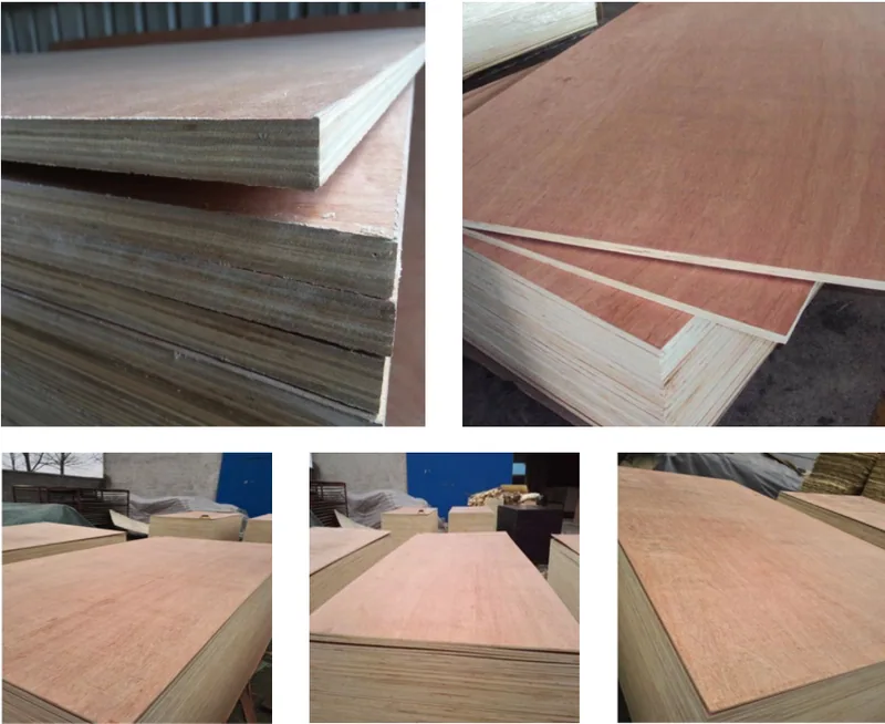
Bintangor faces, layered edges and sheet stacks across the plywood range. Select the face and machined-edge finish for your 6mm component.
Select the face and exposed edge together
Mark edges that remain visible, enter a frame or receive a separate finish. Include a slot, handle opening or routed contour in the sample so the chosen core can be reviewed where machining exposes it.
Choose the show face and reverse around the views your customer sees. A drawer can expose both its inside and underside; a display may be viewed from behind. Select permitted repairs, veneer joints and colour for those surfaces, with adjoining parts grouped before cutting.
Choose the calibrated construction and format
The calibrated technical-data configuration uses 6mm ±0.2mm, giving 5.8–6.2mm before a separately specified finish. Select poplar, combi (poplar/eucalyptus) or eucalyptus core with the Bintangor face, reverse, layup and required machined edge.
The standard formats are 1220 × 2440mm, 1250 × 2500mm and 915 × 2135mm; cut sizes are by enquiry. State grain direction and the dimensions at the delivered and finished stages. Compare the Bintangor plywood range, 4mm thin backs and linings or 12mm components where your assembly needs another section.
USE, CONSTRUCTION & THE COMPLETED SAMPLE
Select the panel around its working detail
Show how the part is supported, which faces remain visible and whether the order covers sheets, blanks or machined components. Start the sample with the receiving joint or contact surface that controls its use.
Three views of the same order: use, construction and acceptance
Component brief
Construction priority
Useful trial
Framed furniture insert
Face selection, perimeter fit and the edge hidden or exposed by the frame.
A finished corner assembled with its retainer and the actual receiving detail.
Drawer bottom or liner
Whether the panel carries the contents or rests on another base; both visible faces.
The complete support and connection arrangement under the specified use.
Cross-slot packing divider
Slot width, effective depth, edge quality, cell size and contact with the goods.
One complete compartment grid with representative goods and protective lining.
Routed display component
Core at curves and apertures, narrow retained areas and finished edge appearance.
The actual contour, smallest opening and intended surface treatment.
Put bare-panel, coated-part and assembled dimensions on the drawing at their respective stages. Keep cut size, finished size and assembly allowance distinct, then include the complete supports, connections or outer pack when setting the performance requirement.
INSERTS, DRAWERS, PACKING GRIDS & DISPLAYS
Choose the component route for your project
Furniture inserts and framed panels
Show the opening, rebate or groove, retainer and insertion route. Mark the visible face and concealed perimeter. For a removable insert, include the grip and release detail and protect the thin edges during removal and refitting.
Review the routed core edge under the proposed finish alongside the coated Bintangor face. Select its appearance where it remains visible after assembly.
Drawer bottoms and supported liners
Provide the drawer opening, contents and support arrangement, including perimeter or intermediate supports. Identify whether the panel carries the load or rests on an existing base, then develop the connection with the complete drawer.
For a replacement, send the receiving detail, entry direction and rear fastening. Sample the supported component with the surfaces seen inside and underneath the drawer.
Packing dividers and compartment kits
Share item dimensions, sensitive surfaces, grid arrangement and outer container. Identify partitions that restrain goods and those that separate them, including end clearances, tray support and protective lining.
Trial a complete grid with the intended goods and outer pack. Include dismantling and reassembly for reusable kits, with handling conditions part of the protection brief.
Routed display components
Mark apertures, internal radii, handle openings and narrow bridges on the outline. Include the stand, base or mounting connection and the installation direction where the part fits another component.
Develop the selected core and finished edge with the carried accessories and supports, keeping the visible face arrangement through machining and packing.
CROSS-SLOT WIDTH, EFFECTIVE DEPTH & SEATING
Set thickness clearance and height alignment separately
Two upright strips interlock with one slotted from the bottom and the other from the top. Slot width receives the crossing strip's finished thickness; effective depth sets the relative height at which the roots meet.
Read the worked detail and calculations
Include the finish at the contacting faces
For a width calculation using a 6.10mm strip and a 6.30mm slot, total clearance is 0.20mm across both faces. These are joint-design inputs. Select the actual slot and finished-panel limits with the coating present at the contact surfaces.
Trial insertion, retention and repeated assembly in the chosen construction, checking the slot mouth and face veneer after use. The bare calibrated range remains 5.8–6.2mm; later finishing is included in the completed-joint dimensions.
Dimension the surface that stops the strip
A rounded slot root can contact a square mating edge before the end of the nominal toolpath. Show the root relief or mating-edge radius and dimension the effective seating depth.
For equal-height strips with flat roots and aligned top and bottom levels, the two opposing effective depths add to the strip height. Review that geometry after machining and finishing.
Compare the depth combinations for a 150mm strip
The drawings show separate strips before assembly, with 150mm height, flat slot roots and a 6.4mm drawn slot width. The width is a drawing input for this depth comparison; the production width follows the selected finished fit.
Depths allow equal top and bottom levelsEach 75mm slot reaches half the 150mm strip height. With ideal flat roots and suitable width fit, the crossed strips can align without a depth shortfall.Short slots leave a height mismatchWith 73mm effective depth from each opposing edge, one strip must sit 4mm higher for the flat roots to meet. Their combined vertical envelope becomes 154mm rather than 150mm.
With 75.5mm effective depth in each slot, the sum is 151mm. At equal top and bottom levels, 1mm remains between the opposing roots; the strips can seat 1mm farther before root contact. Set the final seat and height restraint in the assembly, with withdrawal and retention considered separately.
Include the actual root profile, coatings and machining variation in the effective depths. Review top and bottom alignment on the supported grid before fixing the component drawing and batch settings.
FINISHED CELL SIZE & PARTITION POSITIONS
Size the clear cells around the goods and lining
For this grid calculation, use a 600 × 400mm envelope, four equal columns and three equal rows, with three internal dividers in one direction and two in the other. Start with 6.0mm finished divider thickness.
Subtract the partitions before dividing the clear space
The 600 × 400mm rectangle is the grid boundary. Include end gaps, outer walls, retainers and insertion clearance when locating it in the actual container.
Four columns × three rows; lining is deducted on both sides of each cell
Condition
Clear width
Clear depth
What the figures include
6.0mm dividers
145.50mm
129.33mm
Partitions only
Add 2mm lining per side
141.50mm
125.33mm
Uncompressed lining on opposing faces
6.2mm dividers + same lining
141.35mm
125.20mm
Calibrated bare-panel upper limit with the same lining
Goods measuring 140 × 124mm have approximately 1.50mm and 1.33mm total free space in the lined 6.0mm cells. The totals span each compartment; add item-size variation, protrusions and the selected lining's compression behaviour to the actual packing brief.
The 6.2mm row uses the calibrated bare-panel upper limit with the same uncompressed 2mm lining on each side. It includes no extra coating thickness. Carry any added finish and the most restrictive item dimensions into the completed-grid trial.
Locate slots from the clear-cell layout
At 6.0mm divider thickness, slot centres along the 600mm strips are 148.5, 300 and 451.5mm from one end. Along the 400mm strips they are approximately 132.33 and 267.67mm. These positions place the partitions between equal clear cells.
Equal centre-line spacings of 150mm and 133.33mm describe a different layout. Use one marked datum and retain the intended precision in the production file; the displayed values are rounded for reading. Record end relief and lining before deriving the finished part list.
100 SETS · A AND B BLANKS ON ONE SHEET
Plan complete divider sets with the cutting schedule
The blank schedule uses two A pieces at 600 × 150mm and three B pieces at 400 × 150mm per set, before slots and final perimeter adjustments. Start from a 1220 × 2440mm sheet with 10mm trim at every edge and 3mm kerfs.
Read the worked detail and calculations
The usable rectangle is 1200 × 2420mm. Seven 150mm-wide lanes occupy 7 × 150 + 6 × 3 = 1068mm; eight lanes would need 1221mm. In one lane, two A and three B blanks use 2 × 600 + 3 × 400 + 4 × 3 = 2412mm, within the usable length.
Regular strip layouts with the component length along the sheet length
Lane schedule
Length used per lane
Output per sheet
Use in a 100-set order
Four A blanks
2409mm
28 A blanks
8 sheets for at least 200 A
Six B blanks
2415mm
42 B blanks
8 sheets for at least 300 B
Two A + three B
2412mm
14 A + 21 B = 7 sets
15 sheets provide capacity for 105 sets
Balance the two part quantities
Separate schedules require 8 + 8 = 16 sheets to provide at least 200 A and 300 B blanks. The mixed schedule gives seven sets per sheet: fourteen sheets make 98 sets, and two more mixed lanes on the fifteenth complete 100 sets: 200 A + 300 B = 500 blanks. Allocate the remaining capacity to selected spares or another part.
Fifteen full sheets contain 44.652m² of purchased panel. The 500 rectangular blanks contain 36m², or 0.216m³ at nominal 6mm, before slot removal and finishing. The sixteen-sheet schedule buys 47.6288m².
These are the three specified regular strip layouts. Apply the actual face selection, workholding, grain requirement, squaring allowance and production losses when confirming accepted output. Record useful offcuts by size and condition for the wider order.
Keep the assembly marks with each set
Where face grain follows sheet length, it runs along both the 600mm and 400mm strips in this plan. Mark A/B type, datum end, show face and slot-entry edge before machining. Pair the two part groups with the intended opposing slots.
Quote kits by complete sets with the part count listed. For rectangular blanks, identify slot machining as the remaining workshop scope. For finished sets, include the slot drawing, edge treatment, assembly fit and sample reference in the supplied work.
CUT CORE, SLOT ROOT & FINISHED CONTACT
Develop the part with the actual cutter and coating sequence
Read machining and workshop guidance
Review the core where it is machined
Include a straight edge, cross-grain cut, slot mouth and smallest opening. Inspect local voids, loose fibres, separation and breakout before filling or covering. Keep the unfinished edge reference with the completed sample.
Select the exposed layered edge after its planned finish, with permitted features and veneer-joint appearance recorded alongside the broad face.
Seat the mating part at the root
Coordinate the cutter's internal corner radius with the mating edge or a designed relief. Include material removed beyond the basic slot when checking adjacent holes, narrow bridges and visible edges.
Hold the strip through its final cut
Support the sheet, strip and offcut as slots and outlines are released. Plan tabs or another retained detail with its removal and edge-finishing step, then inspect final width and the slot mouth.
Develop pockets and fixings with their support
Show where each fastener engages its support and how the head bears on the panel. Use the accepted minimum thickness and deepest tool geometry, including points or countersinks, for a blind feature. Trial the hardware in the actual core and completed connection.
Keep fit and finishing in the same process sample
Identify bare, sanded, pre-coated or assembled-and-finished supply. Review the coating inside the slot and on the crossing panel together, with the available decorative-veneer preparation allowance included in the route.
Compare the Bintangor colour under the intended stain or clear finish, including permitted repairs, a cut edge and slotted region. Review the assembled set under its intended lighting and retain the successful preparation and joint detail for production.
SELECTED MATERIAL, SERVICE CONDITION & DOCUMENTS
Choose the construction for the component's intended use
The dried furniture-processing configuration uses 8–12% moisture content. Coordinate receiving condition and workshop preparation before close-fitting machining or bonding. Store panels flat on dry supports and protect the faces from uneven wetting.
Core-specific density ranges are 500–540kg/m³ for poplar, 560–610kg/m³ for combi and 620–660kg/m³ for eucalyptus. The loading reference uses 550kg/m³, with approximately 9.8kg for a 1220 × 2440 × 6mm sheet. Use the selected construction and actual pack data for shipping.
Specify exposure, bond and emissions
Describe humidity, cleaning, possible wetting and contact with damp goods. Select the adhesive, bonding performance and cut-edge protection for that use. Put emission requirements in their own field with method, limit and document scope.
Develop the complete assembly
Include drawer contents and supports, packing goods and cushioning, or the display mounting and applied loads in the sample. Identify fire, durability or other project requirements with the construction and documents needed for that order.
For a curved part, send radius, direction, forming process and support so the appropriate construction can be selected. For laser or other thermal cutting, include material compatibility and machine requirements in the process enquiry.
THE COMPONENT, GOODS & RECEIVING DETAIL
Develop the sample that resolves your assembly
For a divider kit, start with an A/B crossing and then a complete lined grid with its goods and outer pack. For a furniture insert, include a finished corner and retainer. For a drawer bottom, bring the actual supports and connection with the intended duty.
Use the selected face, reverse, core and calibrated supply through the planned machining and finish. Record slot width, effective depth, cell dimensions and final part size where they control the assembly. Keep the drawing revision and sample reference together.
Compare full sheets, rectangular blanks and machined sets with the same appearance selection, finished requirements and included operations. We can begin with a component photo or outline and help complete dimensions, quantities, documents and the useful sample scope.
ACCEPTED PARTS, COMPLETE SETS & PROTECTED PACKS
Carry the assembly reference through inspection and delivery
Inspect each feature at the relevant stage: raw slot, coated joint, unfinished core edge or completed surface. Retain the component sample, drawing revision and batch identity with the measurements and appearance records.
Dimensional, appearance and assembly records serve different purposes
Check
Record
Acceptance basis
Thickness and construction
Core, layup, supplied finish and thickness at agreed positions.
The selected 6mm order limits and measurement condition.
Outer dimensions and slots
Part size, squareness, datum end, slot centres, widths and effective depths.
The current part drawing, including root relief and finished allowances.
Face and cut edges
Show face, reverse, repairs, veneer joints, exposed core and finish.
The agreed visible areas and edge-quality sample.
Assembled divider grid
Top and bottom alignment, insertion, retention, clear cells and lining.
The assembly drawing and trial with the intended goods and container.
Quantity and set identity
A/B part counts, slot orientation, matching group and pack labels.
The complete-set schedule or the stated scope for blanks.
Supply and transport condition
Moisture checks, pack support, edge protection and any receiving damage.
The agreed supply, packing and receiving requirements.
Protect the slots and preserve set identity
Support parts in the pack and protect slot mouths, corners and finished faces. Bundle matching A/B quantities or label the separate groups clearly, with marks kept off the final visible surfaces.
Provide support during transport and unpacking for long narrow pieces. Include face protection, receiving equipment and pack size and mass with the delivery scope. Retain part type, datum and slot-entry marks through assembly.
Send drawings to sales@plywoodsupplier.cn or use the 6mm product enquiry form. We can complete the selected construction, sample, supplied operations and quotation around the accepted components your workshop needs.
PLAN YOUR PANEL ORDER
Get the right parts together, ready for your assembly.
Bring the receiving frame, slot arrangement or packed goods into the panel choice. We help connect the Bintangor appearance, core, finished dimensions and processing in a component sample, then compare the full-sheet, blank or machined-set supply your workshop needs.
6mm Bintangor Plywood
Your receiving detail, finished fit and component quantities
Furniture or divider use, face and selected core
Component or set drawing, fit and finish
Accepted quantities, included processing and destination
Take the selected construction through the intended cuts and coating. For divider kits, review one A/B crossing and a full lined grid with the goods and container. For furniture parts, use the finished corner, frame, support or fitting that controls the assembly.
Standard samples without special work or a logo have no sample charge; delivery is separate. Custom samples are agreed individually.
Order quantity
Our starting guidance is one container for standard sizes and 3,000–10,000 pieces for custom sizes or designs. Tell us your trial quantity.
Production
All products are made to customer order. Production takes 10–15 days; the order confirmation records the start date and production schedule. Sea transit is additional.
Payment
Where a deposit applies, our standard reference is 30% before production, with the balance after inspection and before loading. T/T or L/C terms are agreed for the order.
Shipping
Panel orders ship by container. Share your destination so we can arrange the loading plan and quote the freight separately from production.
After-sales warranty
All products include a 180-day after-sales warranty. Contact our team with the order reference and details of any product concern.
Tell us your quantity, sample needs and target delivery date. We’ll put the price, payment terms and production schedule into your quotation.
Share the material, thickness and test standard your project requires. Our factory team will help you select the product reports and documents for your purchase.
Production & inspection
We can plan production and inspection around your panel specification, with dimensional checks, recorded readings and packing photographs for your order.
We prepare packing details, pack quantities and dispatch documents for your order. Share the destination and receiving requirements so our team can help plan delivery.
Framed furniture inserts, drawer components, supported linings, packing dividers and routed display parts. Start with the receiving frame, support or packing layout. We can help develop the face, core, machined edge and finished sample before quoting sheets or prepared components.
What thickness range applies to the calibrated panel?
The calibrated sanded TDS configuration is 6mm ±0.2mm, or 5.8–6.2mm at that supply stage. Carry any later sanding or coating into the finished joint dimensions. For another supplied condition, include its thickness range and measuring stage in the order.
Which sheet sizes and supply routes can I order?
Standard formats are 1220 × 2440, 1250 × 2500 and 915 × 2135mm. We also quote cut blanks and machined components from your dimensions. For divider kits, list the required complete sets and the pieces of each type within a set.
Which face, core and density belong to this product?
Choose a Bintangor decorative face with the required reverse and selected core. The technical sheet lists poplar at 500–540kg/m³, poplar/eucalyptus combi at 560–610kg/m³ and eucalyptus at 620–660kg/m³. Review the chosen core at the slot or finished edge that stays visible.
How many plies are listed and what does a sheet weigh?
The 6mm transport-table configuration lists 5 plies. A 1220 × 2440 × 6mm sheet has nominal volume 0.0178608m³; at the table’s 550kg/m³ planning density it weighs about 9.8kg. The table gives approximately 2687 sheets per 40HQ on a 26.4-tonne net-panel calculation. Core, packing and route payload determine the actual shipment.
Can you supply parts for a drawer bottom or framed insert?
Yes. Send the drawer opening or frame detail, visible faces, contents and supports. Include the insertion direction, retainers and fastening. We can prepare a fitted component sample and coordinate its dimensions, core and finish with the complete assembly.
How do I set the width of a cross-slot joint?
Use the finished thickness of the crossing strip and the intended joint clearance. A 6.10mm strip in a 6.30mm slot gives 0.20mm total width clearance across both faces. Keep the selected panel range, coating and slot limits on the drawing and check the actual pair for insertion and retention.
Why do cross-slot dividers sit at different heights?
With equal 150mm-high strips and flat seating roots, two 75mm slots allow equal top and bottom levels. Two 73mm slots add to 146mm, leaving a 4mm depth shortfall; one strip then sits 4mm higher and the combined height becomes 154mm. Check the effective root position as well as slot width.
What changes if both 150mm-strip slots are 75.5mm deep?
Their total depth becomes 151mm. At equal top and bottom levels, the opposing roots have a 1mm gap, and the strips can move beyond that aligned position before root contact. Set the intended seat and restraint with the tray or support, then trial the root geometry and finished pair.
How do I make a routed slot seat a square mating edge?
Develop the cutter, closed-end profile and mating edge together. A round cutter leaves a radius that can stop a square part before the intended seating point. Select a compatible edge radius or relief, include nearby holes and narrow material, and check the finished component after coating.
How much room is left inside the divider cells?
For a 600 × 400mm grid with four columns, three rows and exact 6mm dividers, the clear cells are 145.5 × approximately 129.33mm before lining. Deduct the material occupied by the three and two internal partitions respectively, then include the container walls, end clearances and retainers in the complete layout.
How do lining and the upper panel thickness affect the cells?
With 2mm lining on each opposing face, the 6.0mm layout leaves 141.50 × 125.33mm. Using 6.2mm bare dividers with the same lining gives 141.35 × 125.20mm; 6.2mm is the calibrated supplied upper limit before additional coating. Carry the finished divider thickness, goods dimensions and lining behaviour into the packed sample.
How many complete divider sets can one sheet provide?
In the stated 1220 × 2440mm layout, 10mm perimeter trim and 3mm kerfs leave seven 150mm-wide lanes. Each lane fits two 600mm A blanks and three 400mm B blanks, giving seven five-piece sets per sheet. Keep the grain direction, workholding, machining and face selection with the accepted cutting schedule.
How do I plan a 100-set order?
The schedule requires 200 A blanks and 300 B blanks. Fourteen mixed-layout sheets provide 98 sets; two more mixed lanes on sheet fifteen complete 100. Separate A-only and B-only schedules need sixteen sheets in the layouts shown. Compare accepted output and included slot machining, finishing and packing, with a chosen allowance for process loss.
What moisture, exposure and document requirements should I specify?
The dried furniture-processing configuration uses 8–12% moisture. Describe humidity, cleaning or wetting so we can select the adhesive, bond performance and finished-edge protection. Add the required emissions method, limits and sourcing or product documents for your destination, linked to the selected construction.
How can I request a component sample and factory quote?
Send a photo, drawing or compartment layout with sizes, quantity and destination. We can help develop a fitted corner, A/B crossing or complete lined grid, then quote full sheets, blanks or machined sets. Available to order, with 10–15 days production, container shipping, freight terms per order and a 180-day after-sales warranty.
Start with the part photo, frame detail or compartment layout you have. We can help complete the core, face and finished-fit brief, develop a component sample and quote the sheets, cut blanks or machined sets for your order.
Nominal panel thickness: 6mm overall plywood panel, with the delivered and finished machining stages identified.
Calibrated sanded thickness: TDS-PS-01: ±0.2mm at 6mm, giving 5.8–6.2mm at the calibrated supply stage.
Standard sheet sizes: 1220 × 2440mm, 1250 × 2500mm and 915 × 2135mm; custom sizes and cut parts by enquiry.
Have a cross-slot drawing, compartment layout or routed outline? Email it to sales@plywoodsupplier.cn. Start with the details you have; we’ll help you work through the rest.
CONTINUE YOUR PANEL SELECTION
Bintangor plywood construction
Compare our panels
Browse the material range and compare the configurations for your order.
Optional Google Analytics and Ads cookies measure visits and enquiries. Reject keeps these cookies off; basic cookieless measurement continues. Enquiry details are never sent to Google. Privacy details.