A warm wood face, with the joints and cut sizes your workshop needs.
Make cabinet parts, supported shelves and protective packing panels with 12mm Bintangor plywood from our factory. Choose the visible face and core, then bring the joint, finish and cutting schedule together. Send your drawing or part sizes; we will help develop a joined sample and quote full sheets, cut blanks or machined components.
Full sheets, cut blanks or machined components; send the part dimensions, quantity and work to be supplied.
Face and reverse appearance
Show face, reverse, tone, veneer joints, permitted repairs and grading basis selected under the intended finish.
Grain and part sequence
Grain direction, visible areas, matching groups and orientation marked on the cutting schedule.
Squareness
±2mm range reference, with the measurement method and acceptance statement defined for the sheet or component.
Density
520–900kg/m³ across constructions; use the selected construction and actual pack data for handling and freight.
Moisture content
6–12%; delivery target, measurement method and receiving-workshop condition recorded with the order.
Bonding
Phenolic WBP, melamine or MR options; identify the chosen adhesive, bond standard and required test scope.
Emission requirement
Destination requirement, test method, limit and relevant product documents specified separately from adhesive choice.
Standards and product records
GB/T 9846 series and EN 13986 references; identify the applicable part, edition, properties and documents for the selected supply.
Joint and hardware preparation
Mating dimensions, housing depths, fitting model, hole pattern, full tool depth and both-face operations on the drawing.
Surface and edge finish
Bare, prepared or specified finished condition, including edging, coating and finished component dimensions.
Inspection and packing
Accepted sample, drawing revision, construction identity, appearance groups and pack protection connected to the order.
Supply and after-sales
Available to order; 10–15 days production, container shipping, freight terms per order and 180-day after-sales warranty.
Choose the construction, finish and size for your project. We’ll bring the selected options and finished tolerances together in your quotation.
BINTANGOR FACE · JOINED FURNITURE & PROTECTIVE PARTS
Choose the warm wood face and the core behind your component
Bring the Bintangor surface to cabinet parts, supported shelves and protective packing with our 12mm Bintangor-faced plywood. Select poplar or eucalyptus-based construction with the joint, finish and supplied work your workshop needs.
The face veneer is approximately 0.35mm, over the selected core within the 12mm nominal complete panel. Choose the visible face, reverse and permitted repair range under the intended coating, together with the layered edge exposed by machining.
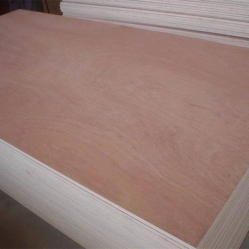
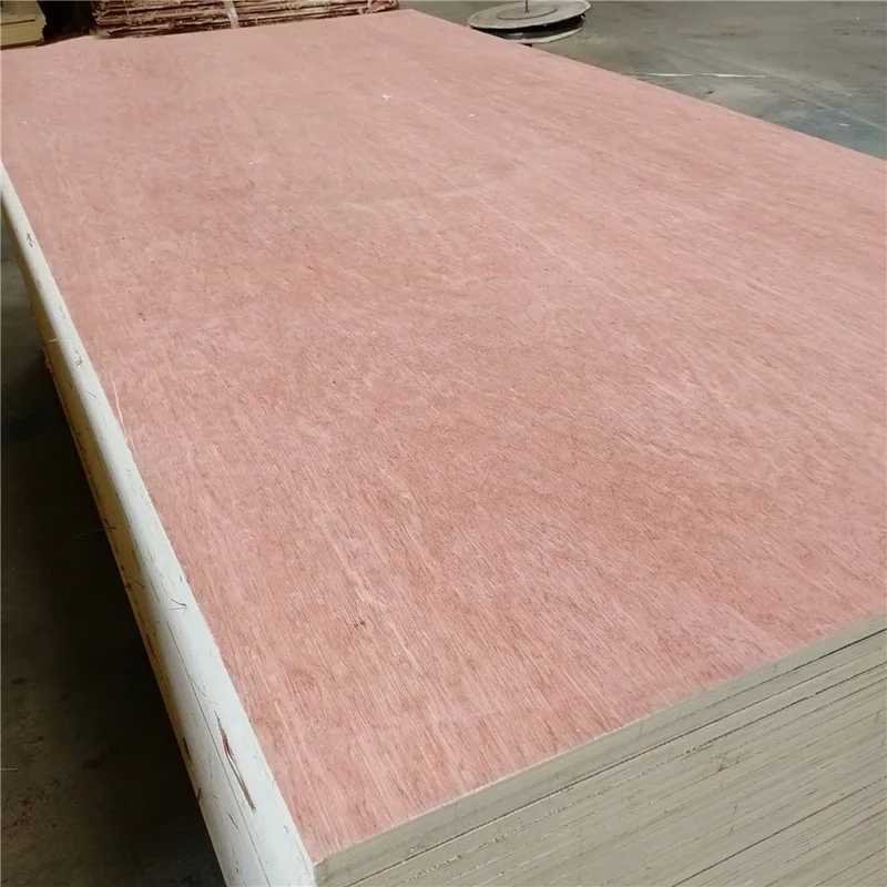
Bintangor-faced plywood stacked in our workshop, showing the warm wood surface and sheet edges. Select the face range, reverse and core with your component sample.
Develop the visible finish
Compare representative colour, grain, repairs and veneer joints under your furniture finish. For protective panels, identify the goods-contact face and outward surface, with cushioning or coating suited to each role.
Select the core around the cut and connection
Include the housing, rebate, connector hole or handle opening in the component brief. Review the exposed edge with the coating, support and fastening detail, then retain the selected construction with the quotation.
Turn the component detail into a comparable quotation
A drawing, photo or the sizes you know can start the order. Choose the detail that matters most in use, then build the face, core and machining sample around it.
The useful sample depends on the component's working detail
Order focus
Specify
Assess on the sample
Visible furniture panel
Show face, reverse, repair range, grain direction and coating.
Several face areas under the intended finish, including a permitted repair.
Housed or rebated joint
Mating thickness, opening, groove depth, cutting length and assembly clearance.
The finished mating pair and material remaining behind the cut.
Hardware-bearing part
Fitting model, hole geometry, fastening method and the selected core.
Installation and use in the actual supported assembly.
Protective packing panel
Goods-contact face, support, fixing, handling and any cushioning.
The complete packing detail with representative goods and contact layers.
Mark the visible face, reverse and exposed edges on the same drawing. Use the grading reference and permitted features with the coated face range to choose the finished appearance.
Request full sheets for your cutting, rectangular blanks ready for the next operation, or machined components with the grooves, holes and finish included. Compare quotations at that same delivered stage, keeping the remaining workshop work with the component schedule.
CABINET PARTS · SUPPORTED SHELVES · PROTECTIVE PANELS
Select the panel around its support and working detail
Cabinet sides and partitions
Plan the outside dimensions, horizontal members and joints together. Mark grooves, shelf-support holes, rear rebates and fittings on both faces so features within the same 12mm section are coordinated.
Identify the face seen from the room or cabinet interior. Carry the selected core, machining datum and thickness limits into repeated modules and their mating parts.
Supported shelves and furniture panels
Send the shelf span, contents, supports and service conditions, including concentrated loads, openings or reinforcement. Develop the complete supported shelf for the loading and deflection your furniture requires.
For a housed shelf, relate cut length to side thickness and groove depths. For hardware support, include the contact and attachment detail in the assembled sample.
Protective plates and packing components
Choose the contact face, cushioning and fixing detail for a separator, protector or supported packing box. Mark exposed edges and staple or screw positions around the goods.
Include lifting, handling, exposure and receiving conditions in the packing brief. Trial the supported assembly with representative goods and contact layers before fixing the supplied configuration.
Routed and rebated parts
Bring the outline, both-face operations and edge profile into one schedule. Mark clear-finished, painted and covered zones, including the layered edge reached by the profile.
Use the smallest aperture, deepest recess and narrowest retained section in the trial. Review those details in the chosen face, core and finish for the production component.
SIDE THICKNESS · GROOVE DEPTH · END CLEARANCE
Calculate the housed part from the complete cabinet width
The ±0.5mm panel tolerance gives 11.5–12.5mm at nominal 12mm. Use the accepted measurement condition and both side thicknesses when setting a horizontal part between two grooved sides.
Outside width − both side thicknesses + both groove depths − total end clearance
For a 600mm outside width, 4mm-deep housing in each side and 1mm total clearance between panel ends and groove roots, nominal 12mm sides give 600 − 12 − 12 + 4 + 4 − 1 = 583mm.
The outside width, housing depths and end clearance are the component dimensions used below. Specify groove width separately for the mating panel’s finished thickness.
Both sides at the stated thickness; fixed 600mm outside width and 4mm housings
Each side
Clear inside width
Groove-root span
Panel length for 1mm total clearance
11.5mm
577mm
585mm
584mm
12.0mm
576mm
584mm
583mm
12.5mm
575mm
583mm
582mm
A fixed 583mm part leaves 2mm, 1mm or zero total end clearance across the three rows. For unequal sides, subtract their individual thicknesses in the formula. Coordinate the part length with groove-depth variation, contact-surface coating and assembly sequence.
Send the close-fitting joint with the component drawing so the factory can quote the finished panel limits and supplied machining together. Review the mating pair after the intended preparation and coating.
BOTH FACES · FULL TOOL REACH · LOCAL SECTION
Coordinate opposing cuts before releasing the part drawing
Overlay front housings, rear rebates, connector pockets and holes at their actual positions. The table uses the 11.5mm minimum panel thickness where two cut footprints coincide.
Read the worked detail and calculations
At overlapping cut footprints: remaining section = 11.5mm − cut A − cut B
Cut from face A
Cut from face B
Calculated section
Geometric meaning
4mm
4mm
3.5mm
Material remains between cuts
5mm
5mm
1.5mm
A thinner remaining section
6mm
6mm
−0.5mm
Cuts overlap by 0.5mm
8mm
5mm
−1.5mm
Cuts overlap by 1.5mm
Review the retained section with the jointThe cuts leave 3.5mm between their footprints. Include the selected core, layup and supported joint in the component trial.The two toolpaths remove the same materialThe red band marks 1.5mm of overlapping cut depth and breakthrough at that shared footprint. Move or revise the machining in the component drawing where a closed section is required.
The common-scale drawings show the depth geometry at the shared tool footprints. Include the core, veneer arrangement, connection and local support when reviewing the working joint. If a feature moves to avoid intersection, keep that revised support and remaining-section detail with the drawing.
Include the full tool-depth range. With each nominal 4mm cut reaching a selected maximum of 4.2mm, the retained section is 11.5 − 4.2 − 4.2 = 3.1mm. Add the actual drill point, countersink or profile where it reaches beyond the specified flat-bottom depth.
CUT EDGE · HARDWARE · PROTECTED DECORATIVE FACE
Keep the raw joint and its finished appearance together
Read machining and workshop guidance
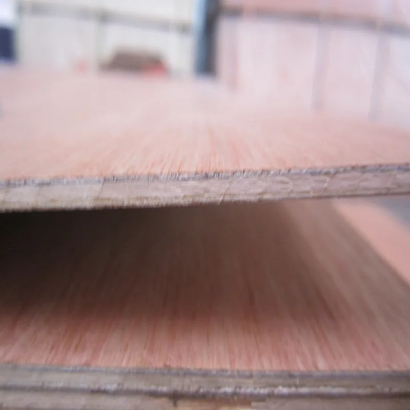
A close view of the Bintangor face and layered plywood edge. Review the selected core after the housing, rebate or profile required by your part.
Review the construction at the cut
Include the intended housing, rebate and drilled feature in the selected layup. Review local joints, gaps, fibres and separation before filling, sealing or banding. Retain that raw cut with the finished edge and drawing revision.
Choose the face-to-edge transition
Compare the Bintangor surface and layered profile under the finish. Keep this reference with the part so repeat orders preserve both the machining detail and the appearance your customer will see.
Prepare the actual fitting
Use the hardware manufacturer’s substrate and preparation requirements. Include model, hole pattern, screw or insert, deepest tool geometry and opposite-face features, then trial installation and operation in the selected core and supported assembly.
Support the sheet and released part
Use the tool maker’s setup with support through the final cut. Review entry and exit faces and cross-grain edges. Keep datum, grain direction and show-face marks in the CNC schedule, with workholding maintained as pockets and outlines are released.
Preserve the face during sizing and finishing
The approximate 0.35mm veneer describes the supplied face layer. A 0.5mm whole-panel sizing correction exceeds that face thickness, so specify tighter panel or mating limits through the manufacturing brief. Agree the actual sanding preparation separately and retain the decorative veneer through the intended stain, primer or clear coat.
Locate from the finished edge
Separate the raw substrate blank from the final outer dimensions, including edging, coating or an added facing. Use the corresponding fitting datum. Keep matching furniture parts and any visible reverse together through colour selection, finishing and packing.
FIVE FORMATS · CONSTRUCTION RANGE · HANDLING PLAN
Choose the sheet format for your parts and workshop
Order 1220 × 2440mm, 1250 × 2500mm, 1500 × 2500mm, 1500 × 3000mm or 2000 × 6000mm in the selected 12mm construction. For the larger format, include machining capacity, receiving access, sheet support and unloading equipment so the factory can coordinate production and protective packing with your workshop.
The 520–900kg/m³ density range covers different constructions. The table compares its endpoints at nominal 12mm volume, excluding packaging and added finishes. Select the core and actual sheet or packed mass for handling and freight.
Nominal 12mm volume × density range; packaging and added finishes excluded
Sheet format
Area
Nominal volume
Calculated panel mass
1220 × 2440mm
2.9768m²
0.0357216m³
18.6–32.1kg
1250 × 2500mm
3.125m²
0.0375m³
19.5–33.8kg
1500 × 2500mm
3.75m²
0.045m³
23.4–40.5kg
1500 × 3000mm
4.5m²
0.054m³
28.1–48.6kg
2000 × 6000mm
12m²
0.144m³
74.9–129.6kg
Compare formats with the joint schedule, cutting output and equipment needed to handle the sheet and released parts. Include actual pack dimensions, mass, support and face protection in delivery planning.
Specify squareness with its measuring method
The range’s squareness reference is ±2mm. Record its measurement procedure and acceptance statement for the chosen sheet size. State length, width and finished-component squareness separately, with the allowances used when squaring and cutting the blanks.
Compare 720 × 480mm blanks across the five formats
The following regular grids use 720 × 480mm rectangular blanks, 10mm trim at every sheet edge and 3mm kerf between blanks. Each column uses one orientation. Add workholding, further machining and face-selection requirements when developing the production nest.
Read the worked detail and calculations
Counts across × along; confirm face-grain direction before rotating
Sheet format
Usable rectangle
720mm along length
720mm across width
1220 × 2440mm
1200 × 2420mm
2 × 3 = 6 blanks
1 × 5 = 5 blanks
1250 × 2500mm
1230 × 2480mm
2 × 3 = 6 blanks
1 × 5 = 5 blanks
1500 × 2500mm
1480 × 2480mm
3 × 3 = 9 blanks
2 × 5 = 10 blanks
1500 × 3000mm
1480 × 2980mm
3 × 4 = 12 blanks
2 × 6 = 12 blanks
2000 × 6000mm
1980 × 5980mm
4 × 8 = 32 blanks
2 × 12 = 24 blanks
On a 1500 × 2500mm sheet, rotation changes the count from nine to ten. Where face grain runs along sheet length, it changes the grain direction within the part too. Choose the orientation that fits the component drawing and accepted appearance.
On 1500 × 3000mm, three 480mm widths and two kerfs use 1446mm; four 720mm lengths and three kerfs use 2889mm. Both fit the 1480 × 2980mm usable rectangle. Include any additional clamp zones or revised squaring process in the final layout.
Compare the purchase needed for 120 parts
Keeping the 720mm edge along sheet length, 120 blanks require 20, 20, 14, 10 and 4 sheets across the five formats. Those grids provide 120, 120, 126, 120 and 128 blank positions before further selection or processing. The required rectangles contain 41.472m² and 0.497664m³ at nominal 12mm, before pockets or profiles are removed.
Ten 1500 × 3000mm sheets purchase 45m²; four 2000 × 6000mm sheets purchase 48m². Compare actual quotations for the accepted quantity and supplied work, together with useful offcuts, handling and packing. Mark grain, show face and permitted repair zones before allocating a visible furniture set.
SERVICE CONDITIONS · MOISTURE · ORDER DOCUMENTS
Select the bond and finished protection for the intended use
The moisture range is 6–12%. Agree the supply target and measuring method with any tighter workshop requirement. Store flat on suitable dry supports, protect edges from wetting and review the condition used for close-fitting machining, finishing and assembly.
Choose the bond with the component
Bonding options include phenolic WBP, melamine and MR. Identify the applicable bond standard and test requirement for the selected construction; include the standard and product scope when a Class 2 requirement is specified.
For a melamine decorative surface, use the separate melamine plywood range. On this Bintangor-veneered product, choose the adhesive, coating and exposed-edge treatment with its intended service conditions.
Request records for the selected supply
State emissions by their required method, limit and product scope. Add any structural, bond or other project documentation to the purchasing brief, with the destination and intended use.
The range references the GB/T 9846 series and EN 13986. Identify the applicable part, edition and product requirements with the quotation and its current conformity or test records.
BSI’s EN 13986 reference covers construction-panel characteristics, conformity evaluation and marking. Apply the relevant product information to the chosen construction and intended use.
For exterior, wet-service, flooring or structural components, send the exposure, support and performance brief. Our team can then coordinate the panel, face protection, cut edges and joints as part of the completed assembly.
MATING PARTS · BOTH-FACE DETAILS · FINISHED SURFACES
Develop the joined component with our factory
Request two mating pieces with the housing or connector and intended coating. Include the closest intersection of both-face cuts, the visible edge and a permitted repair. Review the joint fit and finished appearance in the selected core and support arrangement.
For protective packing, include the support, cushioning and representative goods in the trial. For coordinated furniture, retain the face group and visible reverse with the fitted sample and drawing revision.
Start with sheets, rectangular blanks or machined parts, then specify the cutting, grooves, holes, edge treatment and finish supplied. Compare quotations for that same component stage, accepted quantity and packing scope. The factory team helps complete the details from the application, drawing or finish reference you have.
SELECTED CONSTRUCTION · DRAWING · PROTECTED DELIVERY
Carry the accepted sample through production and packing
Connect the chosen 12mm construction with veneer selection and drying, adhesive application and layup, hot pressing, surface preparation, sanding, cutting and packing. Keep face, dimension and bond checks with the supplied condition and component reference.
Keep the sample, drawing revision and batch identity together
Check
Record
Acceptance basis
Construction and thickness
Actual core, layup, face reference and thickness at agreed positions.
The selected 12mm construction, finished limits and measurement condition.
Outline and squareness
Sheet or blank size, datum, agreed squareness method and cutting allowance.
Quoted sheet requirements or the finished component drawing.
Opposing features
Locations, deepest tool geometry and remaining section at intersecting footprints.
The complete machining drawing and connection requirements.
Face, reverse and exposed edge
Repairs, colour, veneer joints, cut-core features and final surface treatment.
The agreed appearance range and raw/finished edge references.
Bond, moisture and documents
Selected adhesive, supply condition, inspection results and relevant document scope.
The order's test methods, limits and service requirements.
Assembly and shipment
Mating fit, hardware trial, support, part identification and pack condition.
The component sample, supplied scope and agreed packing plan.
Retain the coated face, raw and finished joint, and drawing revision with the order. Keep matched parts identifiable through face separation, edge and corner protection and pack labels. Include receiving equipment, access and storage arrangements when planning larger sheets.
Use actual panel and pack data for freight and unloading. Record arrival condition with the pack reference before parts enter production, and carry any changed fitting or finish into the next order.
Share your drawing through the 12mm product enquiry form or email sales@plywoodsupplier.cn. Start with sizes, quantities and destination; we help complete the face, core, machining and delivery schedule.
PLAN YOUR PANEL ORDER
Turn your component drawing into a useful factory supply.
Choose the Bintangor appearance and construction with the joint, finish and part schedule. Our factory team helps connect the sample to the supplied work and accepted quantities, so your quotation covers the panels your workshop needs to receive.
12mm Bintangor Plywood
Your visible finish, joined component and supplied processing
Component drawing, visible face and finish reference
Core, mating dimensions and both-face toolpaths
Supplied processing, quantities, packing and destination
A joined and coated pair in the selected 12mm construction
Bring two mating parts together with the intended coating and fitting. Include the closest intersection of both-face cuts, then review the joint, exposed edge and finished appearance in the selected 12mm core.
Standard samples without special work or a logo have no sample charge; delivery is separate. Custom samples are agreed individually.
Order quantity
Our starting guidance is one container for standard sizes and 3,000–10,000 pieces for custom sizes or designs. Tell us your trial quantity.
Production
All products are made to customer order. Production takes 10–15 days; the order confirmation records the start date and production schedule. Sea transit is additional.
Payment
Where a deposit applies, our standard reference is 30% before production, with the balance after inspection and before loading. T/T or L/C terms are agreed for the order.
Shipping
Panel orders ship by container. Share your destination so we can arrange the loading plan and quote the freight separately from production.
After-sales warranty
All products include a 180-day after-sales warranty. Contact our team with the order reference and details of any product concern.
Tell us your quantity, sample needs and target delivery date. We’ll put the price, payment terms and production schedule into your quotation.
Share the material, thickness and test standard your project requires. Our factory team will help you select the product reports and documents for your purchase.
Production & inspection
We can plan production and inspection around your panel specification, with dimensional checks, recorded readings and packing photographs for your order.
We prepare packing details, pack quantities and dispatch documents for your order. Share the destination and receiving requirements so our team can help plan delivery.
The decorative face is Bintangor veneer over a poplar or eucalyptus-based plywood construction. Choose the face, visible reverse and actual core with the joint and finish your component needs. We record the selected construction and ply arrangement with the sample and quotation.
Which sheet sizes can I order?
Choose 1220 × 2440, 1250 × 2500, 1500 × 2500, 1500 × 3000 or 2000 × 6000mm, or send custom blank and part sizes. For the larger formats, include the receiving access, handling and processing arrangement so we can plan the supplied work and pack together.
What does the thickness tolerance mean for a close-fitting part?
The ±0.5mm reference gives 11.5–12.5mm at nominal 12mm. Specify the finished limits and measurement condition with the mating groove, connector or housing. If the component needs tighter limits, put them on the drawing so the supplied panel and joint fit can be planned together.
How do I plan sanding and surface preparation?
Choose the supplied surface and coating preparation around the approximately 0.35mm face veneer. A 0.5mm correction removed from one face would exceed that face reference. Set close-fitting panel dimensions through the specified manufacturing limits and mating geometry, then review the actual finish on the sample.
How do I size a panel housed into two cabinet sides?
Use outside width minus both side thicknesses, plus both housing depths, minus the total end clearance. With a 600mm cabinet, two 12mm sides, two 4mm housings and 1mm total end clearance, the cut length is 583mm. Select the depths and clearance for the actual joint and include coating and machining variation.
Does side thickness change the assembly fit?
Yes. For the stated 600mm cabinet, 4mm housings and 1mm total end clearance, sides of 11.5, 12.0 and 12.5mm require lengths of 584, 583 and 582mm respectively. A fixed 583mm part leaves 2, 1 and 0mm total clearance. Use each side’s actual thickness and the complete drawing to coordinate the joint.
How are cuts on opposite faces coordinated?
Overlay the toolpaths at the same position and use the minimum finished thickness. At 11.5mm, two 4mm cuts leave 3.5mm; cuts of 8mm and 5mm overlap by 1.5mm. If two cuts each reach 4.2mm, 3.1mm remains. Include the full cutter or drill-point geometry and review the remaining section with the selected core and joint.
Can you prepare the panel for my hinges or connectors?
Send the fitting model, manufacturer’s preparation requirements, hole pattern and fastening detail. We help coordinate the full tool depth and operations on both faces, then develop the fitting sample in the chosen core and complete assembly.
Can I use this panel for shelves and protective packing?
Yes. For shelves, include the span, contents, supports and connections. For protective packing, show the goods-contact face, cushioning, fixing and handling arrangement. We help select the construction and supplied finish around the working assembly and the performance it needs.
How much does a 1220 × 2440mm sheet weigh?
At nominal 12mm, its volume is 0.0357216m³. Multiplying by the 520–900kg/m³ construction range gives a calculated panel mass of 18.6–32.1kg before packing or added finishes. Use the selected panel and actual pack data for lifting, freight and storage.
How does rotating the cutting layout affect the order?
With 720 × 480mm blanks, 10mm sheet-edge trim and 3mm kerf, a 1500 × 2500mm sheet gives nine positions with the 720mm side along the sheet length, or ten when rotated. Keep grain direction and visible face selection with the drawing before choosing the layout.
Which format uses less material for 120 blanks?
For the stated 720 × 480mm layout with the 720mm side along the sheet length, the five formats need 20, 20, 14, 10 and 4 sheets. Ten 1500 × 3000mm sheets purchase 45m²; four 2000 × 6000mm sheets purchase 48m². Compare the actual delivered quote, accepted parts, useful offcuts and processing with those quantities.
How do I choose bonding and product documents?
Choose phenolic WBP, melamine or MR bonding around the intended use, with the applicable bond standard and test requirements. Melamine bonding can sit beneath a Bintangor veneer face; a melamine decorative face is a separate product choice. Add emission, project and destination documents to the same configuration brief.
What moisture condition and squareness should I specify?
The moisture range is 6–12%; define the supply target, measurement method and workshop needs. The ±2mm squareness reference also needs its own measurement method and acceptance statement. Keep finished part squareness, cutting allowances and the material condition with the component drawing.
What makes a useful pre-production sample?
Develop two mating parts with the chosen face, core, housing or connector and intended coating. Include the closest opposing cuts, visible edge and actual fitting. Retain the joined sample, coated appearance range and drawing revision for production and repeat orders.
What do I need to request a factory quotation?
Send the component drawing or sizes, visible faces, quantity and destination, with any joint or finish reference. We help complete the core, cutting and machining scope and sample plan. Available to order, with 10–15 days production, container shipping, freight terms per order and a 180-day after-sales warranty.
Send a cabinet drawing, packing detail or part sizes and the finish you want. We help complete the construction, joint sample and supply scope for sheets, cut blanks or machined parts.
Nominal thickness: 12mm complete plywood panel.
Finished thickness reference: ±0.5mm: 11.5–12.5mm at nominal 12mm; identify the measurement condition and any tighter component requirement.
Decorative face: Bintangor veneer, approximately 0.35mm face reference; finishing preparation planned around the supplied veneer.
Have a component drawing, joint detail or finish reference? Email it to sales@plywoodsupplier.cn. Start with the details you have; we’ll help you work through the rest.
CONTINUE YOUR PANEL SELECTION
Bintangor plywood construction
Compare our panels
Browse the material range and compare the configurations for your order.
Optional Google Analytics and Ads cookies measure visits and enquiries. Reject keeps these cookies off; basic cookieless measurement continues. Enquiry details are never sent to Google. Privacy details.