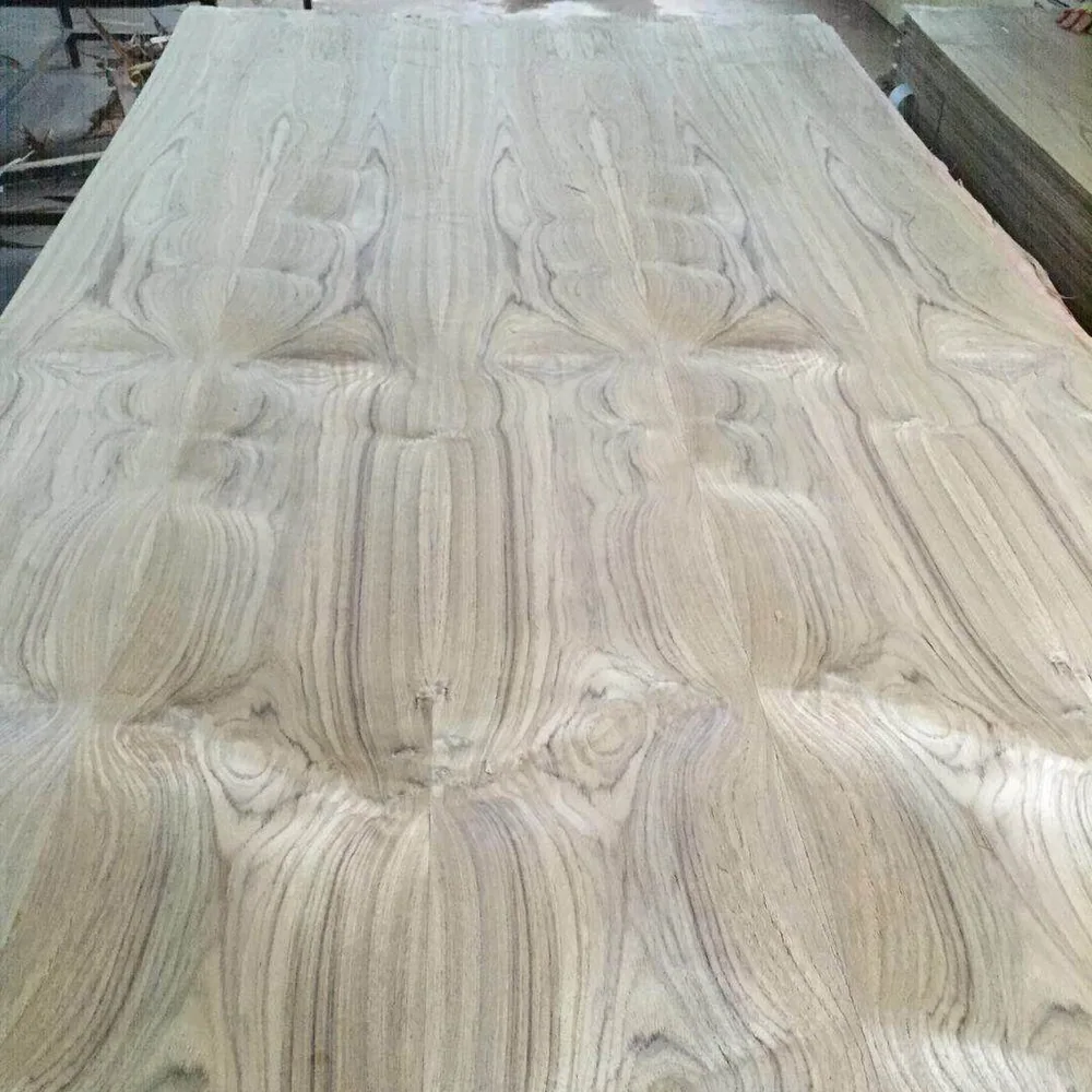
Plan the teak faces, joints and fit as one finished set.
Bring a coordinated teak finish to your wall lining, furniture inserts or display. Our 3.5mm teak-faced plywood can be supplied as sheets or a labelled panel set. Share the elevation, frame or finish you have in mind; our factory helps plan the faces, joints, cut sizes and sample before quoting the production order.
Available to order · 10–15 days production · Container shipping
CONSTRUCTION & SUPPLY CONDITION
3.5mm Teak Plywood specification
Our product configuration and order requirements
Nominal thickness
3.5mm overall plywood thickness; ±0.2mm gives 3.3–3.7mm before added finishes.
Sheet formats
1220 × 2440mm; 1250 × 2500mm; 1500 × 3000mm. Custom sheets and cut panels with the selected 3.5mm construction.
Decorative face
Teak-faced plywood; select the veneer type, figure, colour and coated appearance for the visible elevation.
Reverse side
Specify the reverse independently, including whether it is visible, bonded to a carrier, coated or exposed differently.
Core choices
Poplar, hardwood, birch or eucalyptus; identify the actual 3.5mm layup and internal construction on the order.
Appearance selection
A/A, A/B, B/B or AA/BB as selected for the agreed grading basis, repairs, joints and visible-face limits.
Face veneer and preparation
Choose decorative veneer and supplied sanding with the finish. Keep further preparation within the selected face veneer.
Panel bonding
MR, melamine or phenolic WBP options. State the required bond performance and exposure for the chosen construction.
Emission requirement
E1 or E2 as selected for the intended market and use; specify the applicable test method and required product documents.
Supply moisture
10–15%; set receiving measurements and conditioning with the carrier, processing and installation environment.
Construction joints
Where overlap, end, scarf or finger joints are requested, identify the veneer layer or supplied component, position and accepted appearance.
Lining and openings
Elevation, finished panel sizes, top direction, visible joints, support, retaining profiles and equipment templates.
Factory finish and supply
Full sheets or labelled components, with cutting, openings, edge treatment and supplied coating stage on the drawing.
Sample reference
Two adjoining faces with the actual joint, coating and retaining profile; include a representative service opening or removable detail.
Packing plan
Planning references: 8 pallets/20ft, 16 pallets/40ft and 18 pallets/40HQ. Final pack dimensions, sheets, weight and loading arrangement follow the ordered format.
Factory and documents
Manufactured in Xuzhou, Jiangsu, China. Include the destination, quantity, schedule and applicable product-document requirements with the enquiry.
Choose the construction, finish and size for your project. We’ll bring the selected options and finished tolerances together in your quotation.
TEAK FACE · SELECTED CORE · SUPPORTED LINING
Plan the construction behind the visible teak surface
Our 3.5mm teak-faced plywood is available for supported interior linings, furniture inserts and coordinated access faces. Start with the elevation or component you want to make. We can help choose full-height sheets, smaller panels, removable faces or inserts held in profiles, with the construction and finished appearance identified in your quotation.
For a bonded lining
Show the receiving surface or carrier, planned adhesive and reverse treatment. The completed part includes the plywood, cured adhesive, carrier and finish. Select the plywood's internal bond separately from the adhesive used in your workshop, then include the actual surfaces and finished edge in the sample.
For a framed or profiled lining
Show support positions, joint backing and the retaining detail. Plan fixing, closure and removal with the complete assembly. The profile section and support arrangement help define the panel dimensions and finished thickness that the order needs.
The range offers poplar, hardwood, birch and eucalyptus core choices. Record the selected core and layup for the 3.5mm order together with the teak face veneer type, figure and appearance reference. Choose the reverse for its visible, bonding or sealed role and identify permitted veneer joints with the layer they belong to.
For another thin construction, compare 2mm teak plywood for skins and 2.5mm teak plywood for recessed components. This page develops the elevation, usable sheet height and profile fit of a 3.5mm lining set.
FACE GRADE, FIGURE AND PANEL SEQUENCE
Choose the appearance across the complete elevation
Select the teak face around the whole visible area, including veneer joints, repairs and permitted tone variation. The range's A/A, A/B, B/B and AA/BB face/back choices are defined with their grading reference and accepted appearance sample. Identify the visible front, reverse and areas concealed by trim.
Give each panel a position and viewing direction
Label a four-panel lining A–D, or a split set A1/A2 through D1/D2. Mark top, front and grain direction on the elevation. Show return walls and opposite cabinet sides in their actual viewing positions so face allocation and cutting follow the same arrangement.
Choose coordinated colour and figure, a specified veneer sequence or an intentionally varied arrangement with the actual sample. For a cross-joint, select a continuing figure or deliberate visual break between upper and lower pieces. Keep those identities through trimming, coating and packing.
Use a coated joint sample with the elevation reference. The joint sample records the edge, finish and trim; the elevation records the relationship between the panels.
Coordinate panel height, reveals, perimeter returns and support on one elevation. Include sockets, displays and service details before choosing the format. Select the finish in the intended lighting and connect heavier display fittings to their supporting attachment.
Furniture inserts and wardrobe interiors
Bring the frame or profile and identify the faces visible when the furniture opens. Plan the coated retaining-edge thickness, installation access and removal allowance. For a bonded face, include its carrier and reverse treatment in the sample.
Cabinet backs and access panels
Select the hatch and fixed lining as a coordinated group. Show the supporting frame, openings, closure and access route. Include any cabinet-bracing or attachment duty with that complete construction.
Curved or transport-interior features
Send the shape, radius reference, forming direction and carrier for a representative assembly sample. For cabins or other regulated interiors, include the project's waterproof, marine, fire or emission requirements, expected cleaning and condensation with the proposed construction.
FROM THE ELEVATION TO THE CUT LIST
Choose full-height faces or a deliberate cross-joint
Work from the finished panel rectangles and visible joints, with trimming allowed in the sheet plan. The layout below uses a 3600 × 2480mm envelope, four equal vertical panels, 10mm perimeter space at every outside edge and three 4mm vertical reveals. These are the selected dimensional inputs for the layout.
The schedule is four 892 × 2460mm panels, with the long face direction vertical.
Dividing 3600mm into four 900mm panels would use the entire width before adding joints and perimeter spaces. Keep the full dimension chain with the drawing so the workshop and installer use the same reference.
Divide the height while keeping the joint visible in the schedule
With a 4mm horizontal reveal dividing each panel into two, piece height is (2460 − 4) ÷ 2 = 1228mm. The schedule becomes eight 892 × 1228mm pieces, with the horizontal joint, backing and access detail included in the elevation.
Four full-height facesThe 2460mm part requires enough usable sheet length after trimming. The supporting and fixing detail is added to this elevation.Eight pieces with a horizontal jointThe cross-joint changes cutting yield, edge preparation, face sequence and backing.
The full-height layout has three internal vertical reveals of 2460mm each, totalling 7.380m. Four horizontal segments of 892mm add 3.568m, giving 10.948m of joint centreline in the split layout. Calculate physical trim, adhesive and support quantities from their own overlaps, returns and installation details.
Choose the perimeter and movement detail for the actual installation. Include the surface behind a dark reveal in the sample; for a cover strip, show its visible width, concealed panel area and support on the same elevation.
USABLE HEIGHT, KERFS AND THE COMPLETE SET
Compare sheet formats against the finished panel schedule
Choose from 1220 × 2440mm, 1250 × 2500mm and 1500 × 3000mm. This cutting comparison uses 10mm trim at all four edges, a 3mm kerf and the long grain direction along the sheet length. It counts a regular grid; face allocation, processing allowance and selected spares are added to the order schedule.
Read the worked detail and calculations
Regular fixed-grain grid for full-height panels and jointed pieces
Sheet
Usable rectangle
892 × 2460mm panels
892 × 1228mm pieces
1220 × 2440mm
1200 × 2420mm
0: insufficient length
1 per sheet
1250 × 2500mm
1230 × 2480mm
1 per sheet
2 per sheet
1500 × 3000mm
1480 × 2980mm
1 per sheet
2 per sheet
Two short pieces need 1228 + 3 + 1228 = 2459mm along a sheet. This exceeds both the smaller format's 2420mm trimmed length and its full 2440mm length. Two pieces across need 892 + 3 + 892 = 1787mm, wider than every usable width listed. The 1250 × 2500mm format accommodates one full-height part or two short parts in this layout.
Nominal sheet purchase for one lining elevation, before selection losses or spares
Supply option
Sheets required
Purchased area
Volume at 3.5mm
Four full-height parts from 1250 × 2500mm
4
12.5000m²
0.0437500m³
Four full-height parts from 1500 × 3000mm
4
18.0000m²
0.0630000m³
Eight short pieces from 1220 × 2440mm
8
23.8144m²
0.0833504m³
Eight short pieces from 1250 × 2500mm
4
12.5000m²
0.0437500m³
The four full-height parts contain 8.777280m² of panel; the eight short pieces contain 8.763008m². Their 0.014272m² difference is the area of four horizontal reveals. The larger change in purchased sheet area comes from the format and cutting layout.
Compare the same accepted lining set, face selection, core, bond and supplied stage. Include matching, cutting, finishing, packing and freight, and record any planned use for offcuts separately. For mixed sets, send the complete part list and replacement-piece requirement. Use the chosen construction's actual sheet and pack weights for loading; the table is a volume comparison without a density input.
PANEL, COATING AND RETAINING PROFILE
Check the fit after the surface treatments are included
The ±0.2mm tolerance for the 2–9mm range gives 3.3–3.7mm for the nominal 3.5mm panel before later finishing. Record the required finished limits and measuring condition with the profile detail.
Read the worked detail and calculations
1/8 inch is exactly 3.175mm, which is 0.325mm below 3.5mm. Use the required millimetre dimension and finished interval on the drawing when buying panels and profiles together.
The calculation below adds 0.10mm dry coating to the face and 0.05mm dry treatment to the reverse at the retained edge, then compares that edge with a 3.80mm finished internal profile width. Those coating and profile dimensions are the inputs for this fit check.
Calculated finished thickness and total clearance; dimensions in millimetres
Contribution
Thin end
Nominal panel
Thick end
Uncoated panel
3.30
3.50
3.70
Face plus reverse treatment
0.15
0.15
0.15
Finished panel at profile
3.45
3.65
3.85
Finished internal profile width
3.80
3.80
3.80
Total thickness clearance
0.35
0.15
−0.05
The thick-end result has 0.05mm interference, while the nominal panel has 0.15mm clearance. Include coating variation, profile tolerance, local thickness and any liner or gasket when selecting the finished fit.
Show whether the panel enters a continuous channel, removable bead or clip-on trim, with its internal shape, corners and installation sequence. Keep the profile section beside the elevation so finished width, height, retained edges and insertion route can be checked together.
Choose the receiving detail and supply limits around the panel and its permitted surface preparation. Keep further sanding tied to the decorative veneer while resolving fit through the complete profile and finishing plan.
MATERIAL CONDITION, CUT EDGES AND FINISHED JOINTS
Prepare the lining as a labelled, coordinated set
Read machining and workshop guidance
Plan the material condition for processing
The supplied moisture range is 10–15%. Record the measuring method and compare the panel, carrier and supporting materials with the workshop and installation conditions before precision cutting or bonding. Establish conditioning for the actual construction and receiving environment.
The USDA Wood Handbook chapter on moisture relations describes wood's exchange of moisture with surrounding air. Keep the selected plywood layup and complete assembly with the project movement and handling plan.
Keep the supporting plane and part sequence aligned
Check supports and joint datums against the elevation before fitting the face panels. Choose the assembly adhesive for the actual reverse and carrier and follow its preparation, application and curing requirements. Support the thin sheet through cutting and routing, checking the tool-exit edge on a representative piece.
Label top, face and component ID on a protected reverse area. Distinguish joint edges from outside trim edges. Where installation needs an adjustment allowance, show the specific part and edge carrying it so the joint positions and face sequence remain coordinated.
Review the coating on the actual joint
Select sheen, colour, cleanability and exposure with the coating sample. The USDA Wood Handbook chapter on finishing discusses appearance, protection and compatibility with the wood surface.
State whether coating precedes or follows final trimming and installation. Include the reverse, cut edges and service openings, then recheck the edge entering the profile. A finished sample with two faces, the actual reveal or cover trim, backing and attachment lets you review colour, gloss, joint width and surface step under the project viewing conditions.
CUT-OUT, COVER AND REAR ACCESS
Locate service openings before cutting selected faces
Add sockets, controls, ventilation and access faces to the elevation before allocating the sheets. Use the actual equipment template and support detail, with cut-out dimensions separate from the visible cover and the location measured from a finished-panel datum.
Information to include with each service opening or removable section
Detail
What to show
What to check before conversion
Cut-out geometry
Actual hole dimensions, corner radius and equipment template revision.
Tool access, clean edge production and the finished part size; do not cut from the cover outline.
Position on the panel
Coordinates from finished edges, front-view orientation and component ID.
Top/bottom, handedness and the effect of any later edge trimming on the opening datum.
Cover or bezel
Visible outer dimensions, overlap and nearby reveal or trim.
Concealment of the cut edge, access for installation and clashes with adjacent profiles.
Rear equipment and support
Body depth, cable route, backing or box and attachment points.
Clearance behind the face and the load path into the supporting construction.
Removable access face
Carrier or frame, closure hardware, clear opening and removal direction.
Whether fittings and neighbouring panels allow removal after the lining is complete.
A control beside a vertical reveal needs space for both its cut-out and outer cover. Coordinate any shift needed for backing with the selected figure and rear equipment. Support the opening during machining and inspect the retained narrow strips of face and core.
For an access hatch, identify the decorative skin, carrier and closure hardware separately. Locate hinges, catches or removable fixings into their intended support and check the removal route with the surrounding trim in place. Keep the hatch's face sequence and replacement ID with the fixed lining.
A JOINT, AN OPENING AND THE RETAINING DETAIL
Build a sample around the decisions that affect the set
Start with two neighbouring faces, the selected joint and the actual carrier or support. Include the retaining profile for thickness fit and a cross-joint where the elevation uses one. Add a representative opening, cover and backing detail; demonstrate removal where the finished lining needs later access.
Use the edge and colour sample alongside the elevation reference. For a full-height lining, select an assembly sample that allows the larger joint alignment, face relationship and support detail to be reviewed. Keep its panel IDs, finish and drawing revision with the material selection.
For repeat work, identify changes to the core, finish, support, profile or equipment alongside the earlier accepted reference. The new sample and cutting schedule can then follow the actual assembly you are ordering.
MATERIAL, PANEL IDS AND THE FINISHED INTERFACE
Carry the accepted lining reference through to delivery
Keep the incoming panel, selected face position and finished component linked by their IDs. Use the agreed sample and current drawing at each stage.
Order checks tied to the supplied panel and its place in the elevation
Stage
Inspect
Keep with the result
Incoming sheets
Thickness, dimensions, moisture condition, face and reverse, core and cut-edge condition.
Construction reference, agreed limits, measurement method and order line.
Face allocation
Colour, figure, joints and repairs within each proposed visible component.
Selected reference, sheet identity, top direction and elevation position.
Cut components
Full dimensions, squareness, machined edges, holes and remaining local support areas.
Part ID, drawing revision, equipment template and any remaining trim allowance.
Finished sample
Profile fit, reveal, surface step, finish appearance and the agreed attachment assessment.
Actual support, coating, trim, material condition and measurement stage.
Complete set and packing
All required IDs, matching groups, protected faces, edge support and component count.
Pack sequence, set list, destination marks and designated replacement pieces.
Choose the bond and required documents for the order
Select the internal bond from the range's MR, melamine or phenolic WBP options. Specify the emission requirement, such as E1 or E2, with its applicable test method and destination. Keep adhesive, emission and any fire or other project requirement as distinct items in the purchasing brief.
Send the supplier documents, CE declarations, CARB information or other product records your buyer requires. We can help identify current documents for the actual construction and destination, linked to the quotation and intended use.
Pack the selected sequence for the receiving workshop
The range's pallet planning references are 8 pallets per 20ft container, 16 per 40ft and 18 per 40HQ. Complete the order's load plan with actual pack dimensions, sheets per pack, gross weights, sheet format and route limits.
Provide support and face protection for thin sheets or labelled components. Pack matched sets so IDs, top direction and replacement pieces remain clear on arrival. Our production and quality information explains how the agreed configuration connects to inspection and packing.
Quote the complete 3.5mm lining schedule
Send the elevation, component sizes, quantity per set and accepted appearance reference. Identify the teak face, reverse, core and bond with the cutting, openings, coating and factory work you need. Add matching groups, labels, spares, required documents, destination and delivery timing.
A room, furniture or site photo can start the discussion. Email it with your drawing to sales@plywoodsupplier.cn or use the product enquiry form; our factory team can help complete the sample and order brief.
PLAN YOUR PANEL ORDER
Order the lining set that fits your elevation.
Bring the visible teak appearance together with full-height or jointed panels, profiles and openings. We help compare formats by finished parts and prepare the sample, cutting schedule and labelled set for the same design.
3.5mm Teak Plywood
Your teak face, supporting detail and panel sequence
Lining elevation, panel sizes, top direction and quantities
Teak face, reverse, core, finish and matching groups
Support, profiles, service openings and destination
Two finished faces with their joint and retaining detail
Choose two adjoining faces, the actual reveal or cover trim and the coated retaining edge. Include an opening and its removal detail where needed, then review the sample beside the intended elevation.
Standard samples without special work or a logo have no sample charge; delivery is separate. Custom samples are agreed individually.
Order quantity
Our starting guidance is one container for standard sizes and 3,000–10,000 pieces for custom sizes or designs. Tell us your trial quantity.
Production
All products are made to customer order. Production takes 10–15 days; the order confirmation records the start date and production schedule. Sea transit is additional.
Payment
Where a deposit applies, our standard reference is 30% before production, with the balance after inspection and before loading. T/T or L/C terms are agreed for the order.
Shipping
Panel orders ship by container. Share your destination so we can arrange the loading plan and quote the freight separately from production.
After-sales warranty
All products include a 180-day after-sales warranty. Contact our team with the order reference and details of any product concern.
Tell us your quantity, sample needs and target delivery date. We’ll put the price, payment terms and production schedule into your quotation.
3.3–3.7mm substrate range with the actual coating stack, retaining profile, opening template, support and removal route.
Order and delivery
Accepted coated sample and drawing revision, factory processing, inspection, pack sequence, destination and required document scope.
Product reports for your order
Share the material, thickness and test standard your project requires. Our factory team will help you select the product reports and documents for your purchase.
Production & inspection
We can plan production and inspection around your panel specification, with dimensional checks, recorded readings and packing photographs for your order.
We prepare packing details, pack quantities and dispatch documents for your order. Share the destination and receiving requirements so our team can help plan delivery.
Choose it for supported decorative linings, furniture inserts, displays and coordinated access faces. Share the support or carrier, frame and intended exposure so we can develop the panel and supplied finish around the complete assembly.
How do I choose the teak face and reverse?
Select the veneer type, figure, colour range and finish for the visible face. Choose the reverse for its own role: visible, bonded, coated or enclosed. A coated reference and elevation help keep neighbouring panels coordinated.
Which core options can I specify?
The range offers poplar, hardwood, birch and eucalyptus. We help select the actual 3.5mm veneer arrangement with your support, edge detail and handling needs, keeping the core and its properties with the quoted construction.
Which sheet sizes and cut components are available?
Choose 1220 × 2440mm, 1250 × 2500mm or 1500 × 3000mm, or send your component sizes for custom supply. Include top direction, grain, matching groups, trimming and part quantities so the cutting schedule follows the elevation.
What thickness limits should I use?
The 3.5mm panel uses ±0.2mm thickness limits, giving 3.3–3.7mm before later finishes. Include coating, reverse treatment and the receiving profile in the finished fit. State tighter component limits with the enquiry where required.
Is 3.5mm the same as one-eighth inch?
An exact one-eighth inch is 3.175mm, which is 0.325mm below nominal 3.5mm. Order the written metric thickness and limits for your profile or frame, then check the finished sample with its coating.
Which format can supply a 2460mm full-height lining?
With 10mm reserved at each end, a 2440mm sheet has 2420mm usable length. A 1250 × 2500mm sheet has 2480mm usable length and accommodates the stated 892 × 2460mm panel. Compare the actual part height, grain and trim before selecting the format.
Why can a split lining require more sheets?
In the page layout, each 892 × 1228mm half-panel fits only once in the trimmed 1220 × 2440mm sheet with the stated grain direction. Eight halves therefore use eight sheets. The same elevation uses four 1250 × 2500mm sheets for either full-height panels or paired half-panels, before face selection and spares.
How should I choose the gaps and visible joints?
Develop them with your support, finish, installation conditions and desired appearance. The 10mm perimeter spaces and 4mm reveals in the drawing define its calculation. Put the actual movement, retained-edge and backing detail on the project elevation.
How do I check a coated panel in a retaining profile?
Add the face and reverse treatments to the delivered thickness. A 3.7mm panel with 0.15mm total coating becomes 3.85mm, leaving 0.05mm interference in a 3.80mm finished channel. Include profile and coating variation, then trial the actual finished edge.
How do I plan service openings and removable faces?
Send the equipment template, cut-out coordinates, cover dimensions and rear clearance with the panel ID. Include the supporting carrier, closure and removal direction for access faces, and keep the selected grain sequence with adjoining fixed panels.
Can I order a curved teak-faced component?
Send the shape, radius and intended forming process. We can discuss the selected layup, direction, carrier, edge and finish, then develop an assembly trial for that curved detail.
How should the panels be conditioned before processing?
The supplied moisture range is 10–15%. Plan receiving measurements and conditioning around the panel, carrier, workshop and installation environment. Keep supports level, protect the faces and record the processing condition used for the accepted sample.
Which bond and product documents should I request?
Choose the MR, melamine or phenolic WBP bond requirement separately from the emission class and test method. Send the destination and any CE, CARB, ISO or other document requirements so the relevant scope can be included with the selected construction.
What is a useful sample for a full lining set?
Use two neighbouring faces with the actual joint, coating and retaining profile. Add an opening or access cover where it affects the design. Review finished appearance, fit and removal with the elevation, then retain the sample and drawing references for production.
How do I request a quotation and arrange delivery?
Start with the area, a photo or a panel schedule, plus quantities and destination. We help complete the face, core, factory work and labelled packing. Available to order, with 10–15 days production, container shipping, freight terms agreed per order and a 180-day after-sales warranty.
Send a room or furniture photo, elevation or finish reference. We help choose the face, core and sheet format, then coordinate joints, profiles, openings and samples with the factory quotation.
Sheet formats: 1220 × 2440mm; 1250 × 2500mm; 1500 × 3000mm. Custom sheets and cut panels with the selected 3.5mm construction.
Decorative face: Teak-faced plywood; select the veneer type, figure, colour and coated appearance for the visible elevation.
Have a lining elevation, profile section or opening template? Email it to sales@plywoodsupplier.cn. Start with the details you have; we’ll help you work through the rest.
CONTINUE YOUR PANEL SELECTION
Teak veneer matching and construction
Compare our panels
Browse the material range and compare the configurations for your order.
Optional Google Analytics and Ads cookies measure visits and enquiries. Reject keeps these cookies off; basic cookieless measurement continues. Enquiry details are never sent to Google. Privacy details.