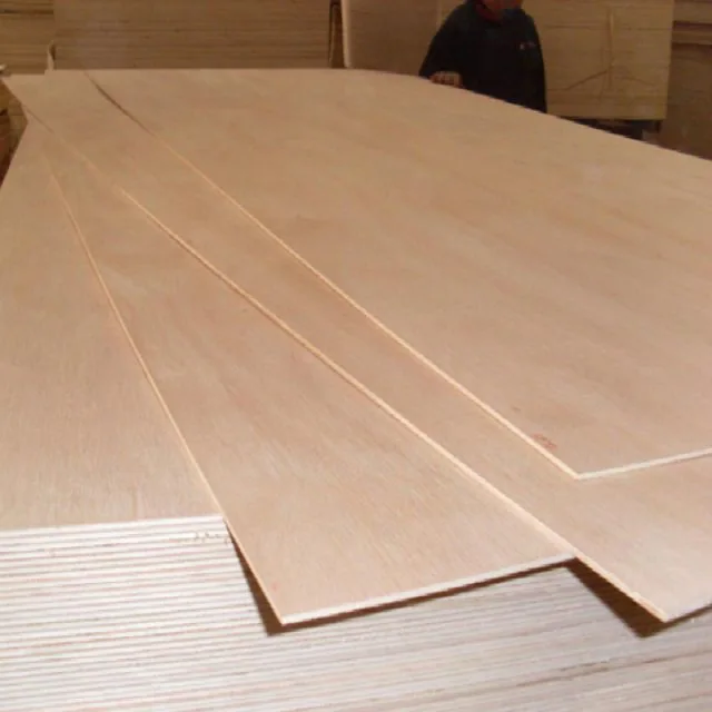
Choose the face and inner construction
Select an all-Okoume, poplar or eucalyptus core with the face, reverse, layup and bond. For a visible scarf, opening or exposed edge, include the cut core and permitted repairs in the finished sample.
PLYWOOD & MDF · CHINA

OUR FACTORY · PRODUCT DETAILS
12mm Okoume panels prepared around the joinery you make.
Bring the Okoume face you want into cabinet inserts, routed panels and longer joined components. Our factory supplies 12mm plywood as full sheets, cut blanks or prepared parts, with the core, reverse and finish selected for your assembly. Send a part photo, sketch or known sizes; we help plan the joint or coating sample, usable lengths and export order.
Available to order · 10–15 days production · Container shipping
TECHNICAL DATA · TDS-PS-06 · Rev 2.0 (Oct 2026)
Choose 12mm Okoume-faced plywood for joinery, coated inserts and machined parts, with the inner veneers selected for the part. The all-Okoume transport configuration below uses a 520 kg/m³ planning density, giving about 18.6 kg per 1220 × 2440 mm sheet. Poplar and eucalyptus cores are separate choices with their own density ranges.
| Face / Back Veneer Species | African Okoume / Gaboon (Aucoumea klaineana, 0.50–1.20 mm thickness) |
|---|---|
| Surface Appearance Grade | B/BB or BB/CC (EN 635-2 / NF B 54-171 Grade II/III) |
| Surface Finishing | Calibrated and fine sanded both sides (150#–180# grit) |
| Core Veneer Options | 100% All-Okoume (Marine/Exterior), Poplar Core (Lightweight), or Eucalyptus Core (High-Strength) |
| Standard Sheet Sizes | 1220 × 2440 mm, 1250 × 2500 mm, 1525 × 3050 mm |
| Thickness Tolerance | ≤ 9 mm: ±0.25 mm | 12–25 mm: ±0.35 mm (EN 315) |
| Adhesive System | Melamine-Urea-Formaldehyde (MUF Class 2) or Phenolic WBP (EN 314-2 Class 3) |
| Service Class / Exposure Duty | Service Class 2 (Humid Interior) or Service Class 3 (Exterior / Marine Joinery) |
| Length & Width Tolerance | ±1.0 mm (EN 315) |
| Squareness | ≤ 1.0 mm / m (EN 324-2) |
| Panel Flatness | ≤ 2.0 mm / m (EN 315) |
| Reference Standards | EN 636-2 / EN 636-3, EN 314-2 Class 2 / Class 3, BS 1088 (100% Okoume option), NF Extérieur CTB-X |
| Harmonized System (HS) Code | 4412.31 |
| Density (All-Okoume / Poplar Core / Eucalyptus Core), kg/m³ | 500–540 / 480–520 / 600–650 Test method: EN 323 |
|---|---|
| Moisture Content at Dispatch, % | 8.0 – 12.0 Test method: EN 322 |
| Bending Strength — Longitudinal (MOR //), MPa | ≥ 42.0 (All-Okoume) Test method: EN 310 |
| Bending Strength — Transverse (MOR T), MPa | ≥ 30.0 (All-Okoume) Test method: EN 310 |
| Modulus of Elasticity — Longitudinal (MOE //), MPa | ≥ 4,900 Test method: EN 310 |
| Modulus of Elasticity — Transverse (MOE T), MPa | ≥ 3,600 Test method: EN 310 |
| Bonding Quality (72h Boil Test — WBP Option), MPa | ≥ 1.0 (Wood failure ≥ 80%) Test method: EN 314-2 Class 3 |
| Screw Withdrawal — Face / Edge, N | ≥ 1,420 (Face) / ≥ 1,020 (Edge) Test method: EN 320 |
| Formaldehyde Release, mg/m³ | ≤ 0.124 (E1) / ≤ 0.05 (E0 / Phenolic) Test method: EN 717-1 |
| Nominal Thickness | Ply Count | Area Weight | Sheet Weight (1220x2440) | Est. Load / 40HQ |
|---|---|---|---|---|
| 3 mm | 3 plies | 1.56 kg/m² | 4.6 kg | ~5,374 pcs |
| 4 mm | 5 plies | 2.08 kg/m² | 6.2 kg | ~4,031 pcs |
| 6 mm | 5 plies | 3.12 kg/m² | 9.3 kg | ~2,687 pcs |
| 9 mm | 7 plies | 4.68 kg/m² | 13.9 kg | ~1,791 pcs |
| 12 mm | 9 plies | 6.24 kg/m² | 18.6 kg | ~1,343 pcs |
| 15 mm | 11 plies | 7.80 kg/m² | 23.2 kg | ~1,074 pcs |
| 18 mm | 11 plies | 9.36 kg/m² | 27.9 kg | ~895 pcs |
| 22 mm | 13 plies | 11.44 kg/m² | 34.1 kg | ~732 pcs |
| 25 mm | 15 plies | 13.00 kg/m² | 38.7 kg | ~644 pcs |
The mechanical figures above describe the all-Okoume construction; retain the selected core and bond with the quotation. The loading table uses 1220 × 2440 mm sheets at 520 kg/m³ and approximately 48 m³ of panel volume. Other cores, finishes, packing and route payload limits change the final shipment weight and quantity.
This 18.6 kg all-Okoume transport configuration is separate from the rounded 20 kg material-planning reference used in the joinery section below. Use the selected core and supplied finish for the order weight.
OKOUME FACES, CHOSEN CORES AND PREPARED COMPONENTS
Choose 12mm Okoume Plywood for a visible wood face on joinery, coated inserts and machined components. Send a project photo, desired finish or known part sizes; our factory team helps connect the appearance, construction and supplied preparation to your next workshop operation.
Select an all-Okoume, poplar or eucalyptus core with the face, reverse, layup and bond. For a visible scarf, opening or exposed edge, include the cut core and permitted repairs in the finished sample.
Specify the cutting, joint preparation, coating or final trimming you want supplied. Keep rough-blank allowances with the later operations and identify the finished dimensions used for assembly.
The technical configuration offers 1220 × 2440mm, 1250 × 2500mm and 1525 × 3050mm sheets, with both sides calibrated and fine sanded at 150#–180#. Its 12mm ±0.35mm thickness range is 11.65–12.35mm; carry the selected supply limits into the part drawing.
Use our Okoume plywood range to compare thicknesses. The 9mm page develops lighter components, while the 18mm page develops a thicker option. Select the core, joint and hardware around the thickness ordered.
START WITH THE RESULT YOUR WORKSHOP NEEDS
Begin with the visible finish, receiving part or overall length you want to achieve. We can help complete the material and sample brief, then put the controlling dimensions and operations into the drawing.
| Component detail | Decision to resolve | What we need |
|---|---|---|
| Clear-finished face and exposed edge | Accepted veneer appearance and local core condition after machining. | Face sample, show-edge locations, grain direction and finish reference. |
| Coated panel in a channel | Finished panel thickness versus the finished clear opening. | Both part sections, dimensional limits and coating build on each mating surface. |
| Component longer than one sheet | Permitted joint, overlap, usable length and final trimming. | Joint drawing, component length, joint locations and design acceptance criteria. |
| Named marine requirement | Actual panel construction and evidence required by the project. | Standard and edition, component duty, core/bond requirements and document scope. |
Compare quotations at the same supplied stage. Include plywood, specified processing, samples, documents and packing so each offer covers the material and work your workshop will receive.
JOINERY INSERTS, LONG PARTS AND ROUTED PANELS
Show the frame, groove or channel and the finish. Identify surfaces coated before assembly, bonding areas and any removable access. Compare the completed insert with its finished mating piece after the operations that affect fit.
Send the finished length, grain direction and available joint drawing. Plan usable input lengths and joint locations with the supports, openings, later trimming and attachment details. The material schedule follows the designer's connection and performance requirements.
Mark cable passages, ventilation slots or access openings. Select the face, cut core and repairs under the clear or opaque finish, including internal corners and all newly exposed edges in the coating sequence.
Identify the component and service conditions with its supports, finish and construction requirements. Where a marine specification controls the purchase, start with our 12mm marine plywood enquiry and the named standard and documents.
CORE-SPECIFIC TRANSPORT AND MATERIAL-PLANNING WEIGHTS
A 2440 × 1220 × 12mm sheet has an area of 2.9768m² and a volume of 0.0357216m³. The all-Okoume transport configuration uses 520kg/m³, giving approximately 18.6kg per sheet with 9 plies.
The density ranges are 500–540kg/m³ for all-Okoume, 480–520kg/m³ for poplar core and 600–650kg/m³ for eucalyptus core. Keep each selected core and supplied condition with its handling and loading figures.
The comparison below uses a 20kg per-sheet planning reference for 12mm. Dividing by 2.9768m² gives approximately 6.719kg/m². This rounded material budget is separate from the named 18.6kg all-Okoume transport configuration.
| Nominal thickness | Planning sheet weight | How to use the reference |
|---|---|---|
| 3mm | 5kg | Compare only with the selected 3mm construction. |
| 5mm | 8kg | Confirm the required configuration by enquiry. |
| 9mm | 15kg | Use the separate 9mm specification for an order. |
| 12mm | 20kg | Input for the separate material-planning comparison. |
| 15mm | 25kg | Confirm core, bond and supply condition. |
| 18mm | 29kg | Confirm core, bond and supply condition. |
| 20mm | 33kg | Confirm the required configuration by enquiry. |
| 25mm | 41kg | Confirm the required configuration by enquiry. |
Use the selected construction's density, moisture, layup and actual dimensions in the order. The rounded thickness comparisons help organise the initial material schedule; the quotation identifies the configuration being supplied.
Add the joint, edging, resin, glass cloth, paint and fittings to the bare-panel weight. Where handling mass controls acceptance, weigh a completed sample. Record pallets, packing and support boards separately when preparing gross shipment data.
LONG COMPONENTS AND TAPERED CONNECTIONS
A scarf joint overlaps the mating tapered ends along the panel length. Here the ratio means horizontal bevel run : panel thickness. At a 12mm section, an 8:1 run is 96mm and a 12:1 run is 144mm. The sloping bond-line length is a separate geometric measurement.
The diagrams use the same scale, with colours distinguishing the mating parts. Select the required ratio, core, layup, adhesive space and connection design for the component; use the overlap to calculate the material length.
When a drawing controls an 8:1 ratio, panel thickness inputs of 11.8mm and 12.2mm give runs of 94.4mm and 97.6mm. These two selected machining inputs are within, but do not represent the full 11.65–12.35mm supply range.
Identify whether ratio or fixed run controls the joint, with the measuring datum and permitted part dimensions. Connection strength and service requirements belong with the selected joint design and component evaluation.
WORKING LENGTH, OVERLAP AND FINAL TRIMMING
Starting with a 2440mm sheet, 10mm trim at each end leaves 2420mm working length. With one 96mm overlap, two untrimmed lengths give 4784mm; two trimmed lengths give 4744mm. Both input pieces carry their own end-trim allowance.
| Selected ratio | Overlap per joint | Two pieces / one joint | Three pieces / two joints |
|---|---|---|---|
| 8:1 | 96mm | 4744mm | 7068mm |
| 10:1 | 120mm | 4720mm | 7020mm |
| 12:1 | 144mm | 4696mm | 6972mm |
Joined length = total working lengths − total overlaps. For a 6000mm target with two 96mm overlaps, the working lengths total 6192mm. Three equal pieces are 2064mm each: 3 × 2064 − 2 × 96 = 6000mm.
Adding final trim of 10mm at each end of the complete assembly gives a pre-trim target of 6020mm and an input total of 6212mm. Locate the joints around supports, openings and visible grain, changing the individual input lengths where the design requires.
Combine the length schedule with finished width, grain direction, width trim and saw kerfs. Narrow strips can share a sheet; full-width parts use the available sheet width. Include face selection, edge cleanup, trial pieces and the agreed process allowance.
Choose full sheets, cut input pieces or accepted joined components for the quotation. The cutting layout and component count connect the geometric length to the quantity purchased.
FINISHED PANEL THICKNESS AND FINISHED CHANNEL OPENING
The first calculation uses a 12mm panel with 0.40mm on each face, giving 12.80mm finished thickness. A 13.50mm bare channel with 0.15mm on each inside wall finishes at 13.20mm. Total geometric clearance is 0.40mm.
The three rows below use their own panel, coating and channel inputs to compare fit. They are joint-design combinations; set the production calculation from the actual 12mm ±0.35mm panel limits and the selected finishing and channel limits.
| Calculation inputs | Finished panel | Finished channel | Channel minus panel |
|---|---|---|---|
| Nominal inputs | 12.00 + 2 × 0.40 = 12.80mm | 13.50 − 2 × 0.15 = 13.20mm | +0.40mm |
| Tight combination | 12.20 + 2 × 0.50 = 13.20mm | 13.40 − 2 × 0.20 = 13.00mm | −0.20mm |
| Loose combination | 11.80 + 2 × 0.30 = 12.40mm | 13.60 − 2 × 0.10 = 13.40mm | +1.00mm |
The tight combination produces 0.20mm interference, while the loose combination gives 1.00mm total clearance. Total clearance divides equally at the two faces only when the panel is centred. Include alignment, bow, corner roots and local coating build where they affect insertion.
Set measuring locations after the specified cure and finishing steps. Include any gasket, liner or adhesive with the required assembly clearance; the selected adhesive and connection design determine the bond-line geometry.
Develop a sample with the actual panel, finish and mating piece. Coordinate adjustments to machining and coating while keeping the agreed veneer preparation and edge protection, then retain that process in the order.
BOTH FACES, OUTSIDE EDGES AND CUT-OUT WALLS
For a rectangle of length L, width W and thickness t, both faces and all four outside edges total 2LW + 2t(L + W). Use one unit throughout, then apply the selected finish system's coverage and process allowance to that area.
For 2.440 × 1.220 × 0.012m, both faces total 5.9536m²; the four edges add 0.08784m², giving 6.04144m². Cutting separate pieces introduces more edges, so take off the finish from the actual component geometry.
| Geometric contribution | Calculation in metres | Surface area |
|---|---|---|
| Both full rectangular faces | 2 × 0.400 × 0.800 | 0.6400m² |
| Four outside edges | 2 × 0.012 × (0.400 + 0.800) | 0.0288m² |
| Total before an opening | 0.6400 + 0.0288 | 0.6688m² |
| Subtract two 150 × 250mm face openings | −2 × 0.150 × 0.250 | −0.0750m² |
| Add the four opening edges | 2 × 0.012 × (0.150 + 0.250) | +0.0096m² |
| Total after the rectangular opening | 0.6688 − 0.0750 + 0.0096 | 0.6034m² |
The 150 × 250mm rectangle is one through-opening: subtract its area from each face and add its four cut walls. The calculation uses straight sides and square corners. Add actual radii, rebates and other machined surfaces from the drawing. For 50 components, the full rectangles total 33.44m²; the same parts with the specified openings total 30.17m².
Use the selected manufacturer's coverage, preparation and layer schedule. Separate face sealing, cut-edge treatment, joint adhesive, fairing and glass wet-out where their materials or rates differ. Mix resin and hardener on that system's stated basis.
A trial on the veneer and cut core establishes the production allowance for absorption, resin-to-glass ratio, equipment loss and reserve. Keep this material allowance with the geometric surface take-off when ordering the finish.
SELECTED VENEER, CUT CORE AND COMPLETE FINISH
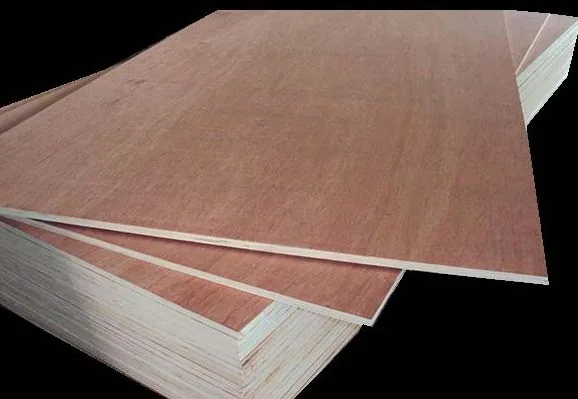
Choose colour, grain, visible joints and repair range under the intended clear or opaque coating. Compare finished samples in workshop and installation lighting, including any joint crossing the show face.
Review the scarf, routed opening or fixing region for core condition, breakout and repairs. Retain an uncoated section with the finished sample, keeping the core and face identities connected.
Use the chosen datum, workholding and joint section. Check the meeting bevels, aligned face and fixture support. For long parts, include the local joint and overall alignment or handling requirement in the trial.
Choose tools and preparation for the supplied face and core. Record the delivered surface and further removal within the decorative veneer's allowance, following the resin or coating system's cleaning and preparation instructions.
Keep cured-epoxy surface preparation, contamination removal and recoating stages in the finishing plan, separately from preparing bare plywood for bonding.
Where the design specifies glass reinforcement, record cloth type, weight, orientation, overlaps and terminations with the resin system. Include overlap and edge-return build in the fit sample; the design defines reinforcement and strength requirements.
Schedule treatment of edges exposed by later holes and cuts. Mark bonding zones and removable interfaces before coating, and check hard-to-access surfaces at the agreed cure stage. For exposed service, select a compatible paint or varnish system with its sunlight protection and maintenance requirements.
FACTORY PREPARATION AND YOUR WORKSHOP HANDOVER
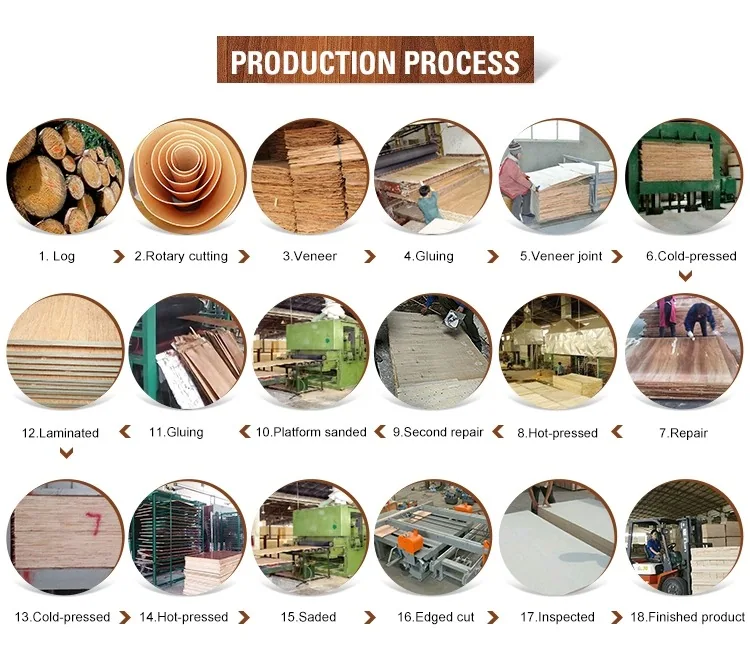
Identify the face, reverse, actual core, layup and bond in the quotation. Keep the coated sample and its demanding machined edge with that configuration.
Record the current revision and any change to joint ratio, finished thickness, grain or coating. Update the cut list and sample reference together.
Define the surface and processing stage your team will receive, including incoming checks where it completes jointing or coating. See our production and quality information for the wider factory process.
THE SELECTED PANEL AND ITS PROJECT DOCUMENTS
For marine work, send the component duty, standard and edition with the core, bond and finish requirements. We can connect the proposed panel with the applicable product report, certification, material declaration or other requested record.
For hulls, decks, structural bulkheads and other load-bearing parts, include the responsible designer's material and joint specification. Its loading, span, bend and structural requirements guide selection and evaluation of the assembled component.
Start with 12mm marine plywood when a marine specification controls the purchase, or Okoume marine plywood when that construction is required. Keep each document request with the actual core, thickness, bond and supplied configuration.
A JOINT, INSERT OR FINISHED EDGE TO COMPARE
Start with the use, a part reference or the finish you want. We can help complete the face, core and supplied preparation before developing the drawing and sample.
Send the mating section or a part photo. Include the bare and finished dimensional limits, show face and coating on each surface, with any gasket, liner, fixing or adhesive. Assess the panel beside its finished receiving piece.
Send the final length, width, grain direction and available joint detail. Define input allowances, joint locations, machining and bonding responsibilities, with final trimming and the component's acceptance requirements.
Include the most demanding exposed edge and desired wood appearance in the coating trial. Keep the accepted construction, process and dimensional record with the sample so the factory and workshop can follow the same reference.
Send drawings and finish references to sales@plywoodsupplier.cn or use the product enquiry form. Add quantity, destination and timing when known; we can complete the sample and order brief with you.
ACCEPTED PARTS AND PROTECTED DELIVERY
Link incoming sheets, machined details and finished assemblies to the selected sample and drawing. Agree measuring locations, methods and limits for the supplied stage, with application-specific evaluation where the project requires it.
| Inspection stage | What to examine | Record with the sample |
|---|---|---|
| Incoming sheet | Face/back appearance, actual dimensions, flatness condition and selected construction. | Material identification, drawing revision, measuring method and accepted limits. |
| After machining | Scarf or routed-edge condition, breakout, core gaps, mating profile and usable length. | Uncoated section, joint dimensions, orientation and local acceptance criteria. |
| After the specified finish | Finished thickness, local build-up, covered edges, face appearance and mating fit. | Finish system, completed operations, cure condition and final dimensions. |
| Complete component | Assembly operation and any required application-specific performance. | Included fittings, support, test scope, acceptance result and retained reference. |
List the core, face, reverse, actual dimensions and quantities by line. Separate whole sheets, prepared joint pieces and completed components, identifying the included machining, coating, trimming, documents and labels.
Choose flat support and face or edge protection for the delivered stage. Protect machined tapers and show edges, carry sample and production identifiers into the packing list, and use actual pack dimensions and gross mass for shipment planning.
PLAN YOUR PANEL ORDER
Connect the finish you want to the construction, working lengths and mating details of the part. Our factory helps plan a useful sample and quote the material, preparation and protected supply for your next operation.
12mm Okoume Plywood
An Okoume component and the part it must meet
Use the actual joint, opening or mating piece with the selected core and coating. Review the bare cut edge before finishing and the completed fit afterwards, keeping the approved drawing and project documents with the sample.
Review this product’s sample planFor a quotation, add your quantity, destination and required timing. You can start with the details you already have.
PanelSource · Xuzhou PanelSource Co., Ltd.
https://www.plywoodsupplier.cn/product/12mm-okoume-plywood/
sales@plywoodsupplier.cn
SAMPLES & ORDER PLANNING
Tell us your quantity, sample needs and target delivery date. We’ll put the price, payment terms and production schedule into your quotation.
DOCUMENTS & ORDER SUPPORT
We help your purchasing team gather product reports, inspection records and packing documents for your order.
Product reference: 12mm Okoume Plywood — specification.
Share the material, thickness and test standard your project requires. Our factory team will help you select the product reports and documents for your purchase.
We can plan production and inspection around your panel specification, with dimensional checks, recorded readings and packing photographs for your order.
Plan the inspection scopeWe prepare packing details, pack quantities and dispatch documents for your order. Share the destination and receiving requirements so our team can help plan delivery.
Review the delivery scopeStart with your application or panel reference. Our team will help with the specification and documents.
PRODUCT-SPECIFIC QUESTIONS
Select all-Okoume, poplar or eucalyptus around the component, cut edges, weight and service requirements. Keep the inner veneers, reverse and bond with the quotation; the technical table identifies the density range for each core and the mechanical data for all-Okoume.
The main sheet is 1220 × 2440mm, with 1250 × 2500mm and 1525 × 3050mm also in the TDS. At 12mm, its thickness reference is ±0.35mm, or 11.65–12.35mm. Add custom part sizes, finished limits and the supplied stage to your enquiry.
The all-Okoume transport table uses 520kg/m³ and a 9-ply 1220 × 2440 × 12mm construction, giving about 18.6kg. The joinery range retains a separate rounded 20kg material-planning reference. Nominal sheet area is 2.9768m² and volume is 0.0357216m³; use the chosen core, finish and actual packing for the order weight.
Add the finish on both panel faces and subtract it from both channel walls. The stated comparison gives 0.40mm total clearance at its nominal inputs, 0.20mm interference at its tight combination and 1.00mm clearance at its loose combination. Put the actual panel, coating and channel limits into the finished-joint drawing.
Use the selected coating system and component design to set the layer schedule and finished build. The fit comparison uses dimensional inputs, including 11.8mm and 12.2mm wood sections; these are separate from the TDS supply range of 11.65–12.35mm. Review the actual cured sample at the agreed measuring stage.
With the ratio defined as horizontal bevel run to panel thickness, 8 × 12 gives 96mm overlap along the panel. A 12:1 ratio gives 144mm. Keep the designer’s joint specification with the selected core, adhesive and component; the sloping bond-line length is a separate measurement.
With one 96mm overlap, the geometric total is 4784mm before trimming. If each input first loses 10mm at both ends, each working length is 2420mm and the joined total is 4744mm before any further end finishing. Include every trimming stage in the cut schedule.
With two 96mm overlaps, working input lengths must total 6192mm. Three 2064mm pieces give 6000mm before further trimming. If the assembled part also loses 10mm at each final end, the pre-trim target is 6020mm and input lengths must total 6212mm. Select the joint positions with the component design.
Use the joint detail selected for the component’s loading, supports and service. Connect the ratio with veneer continuity, adhesive, preparation, alignment and cure. The length schedule then converts that design into working inputs and the quantity of accepted joined parts.
At 2440 × 1220 × 12mm, both faces total 5.9536m² and the four edges add 0.08784m², giving 6.04144m². Apply the selected system’s coverage and layer schedule to those surfaces, including the actual process allowance. Separate components create additional edges.
Subtract the removed area from both faces and add the opening’s internal edges. A 400 × 800 × 12mm rectangle totals 0.6688m²; with the stated rectangular 150 × 250mm opening, it totals 0.6034m². For fifty parts those areas are 33.44m² and 30.17m². Include actual corner radii and rebates in the final take-off.
Compare the selected face, veneer joints and permitted repairs under the intended finish. Include the machined edge and any visible panel joint, then carry grain direction and part sequence into the adjoining components. Retain the selected bare construction with the finished reference.
Review the actual core at the scarf, routed opening and fixing detail. Keep the accepted edge condition, local repairs, breakout and mating geometry with the panel identity and drawing revision, then check the completed appearance and fit after finishing.
Yes. Send the part’s duty, core and bond requirements, named standard and edition with the project document needs. We help select the 12mm construction and supporting evidence, including the all-Okoume option where specified, alongside the proposed coating and assembly.
Choose the stage your workshop wants to receive and include the specified machining, glass reinforcement or finish. We help coordinate the supplied operations and remaining workshop work with the accepted sample, drawing and quotation.
Select support, face protection and edge protection for the supplied stage. Include part IDs, grain direction and drawing revisions on the packing list, protecting tapered ends and coated surfaces. Use the actual packed dimensions and gross weight for the export shipment.
Start with the use, a part photo, finish reference or known sizes. Add quantity and destination; we help complete the core, reverse, bond, joint or opening detail and supplied stage. A mating component or relevant project specification helps define the sample.
Panels are available to order with 10–15 days production and container shipping. Freight terms follow the specific order, with a 180-day after-sales warranty. Contact our team with the order and issue details to agree the handling or replacement arrangement.
CONTACT OUR FACTORY
A part photo, sketch or known sizes is enough to begin. Share the finish, quantity and destination; we help complete the construction, joint details and supplied stage, then prepare the sample and factory quotation.
Have a joint section, coated-fit detail or project specification? Email it to sales@plywoodsupplier.cn. Start with the details you have; we’ll help you work through the rest.
Tell us your panel, dimensions, quantity and destination port.