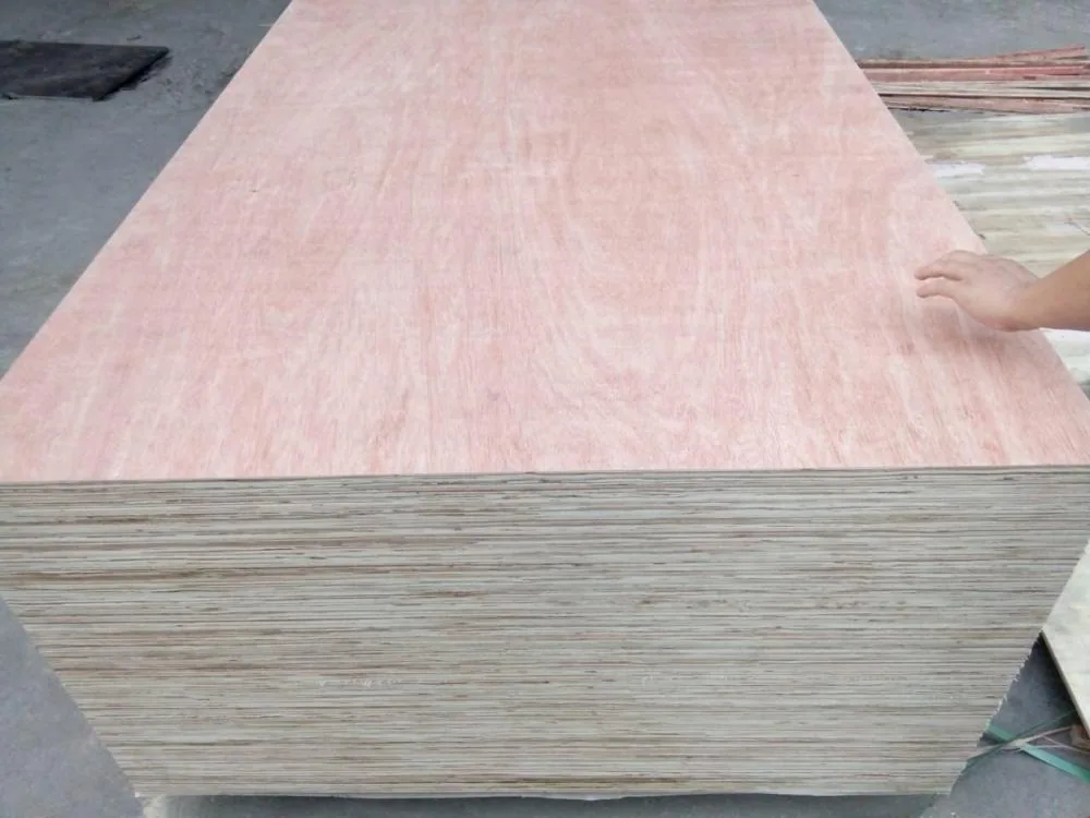
An Okoume finish your customer sees, in a part that fits and handles well.
Build removable covers, framed cabinet inserts and interior components with 9mm Okoume plywood from our factory. Choose the face and core, then plan the openings, finished edges and fittings around the part. Send a drawing or photo; we will help develop a fitted sample and quote sheets, cut blanks or machined components, including a finished-weight target where needed.
Available to order · 10–15 days production · Container shipping
TECHNICAL DATA · TDS-PS-06 · Rev 2.0 (Oct 2026)
9mm Okoume Plywood technical data
Choose 9mm Okoume-faced plywood for fitted furniture inserts and cabinet components, with the inner veneers selected for the part. The all-Okoume transport configuration below uses a 520 kg/m³ planning density, giving about 13.9 kg per 1220 × 2440 mm sheet. Poplar and eucalyptus cores are separate choices with their own density ranges.
Declared values from our technical data sheet TDS-PS-06, Rev 2.0 (Oct 2026). The values for your order are confirmed in the quotation.
Face / Back Veneer Species
African Okoume / Gaboon (Aucoumea klaineana, 0.50–1.20 mm thickness)
Surface Appearance Grade
B/BB or BB/CC (EN 635-2 / NF B 54-171 Grade II/III)
Surface Finishing
Calibrated and fine sanded both sides (150#–180# grit)
Core Veneer Options
100% All-Okoume (Marine/Exterior), Poplar Core (Lightweight), or Eucalyptus Core (High-Strength)
Standard Sheet Sizes
1220 × 2440 mm, 1250 × 2500 mm, 1525 × 3050 mm
Thickness Tolerance
≤ 9 mm: ±0.25 mm | 12–25 mm: ±0.35 mm (EN 315)
Adhesive System
Melamine-Urea-Formaldehyde (MUF Class 2) or Phenolic WBP (EN 314-2 Class 3)
Service Class / Exposure Duty
Service Class 2 (Humid Interior) or Service Class 3 (Exterior / Marine Joinery)
Length & Width Tolerance
±1.0 mm (EN 315)
Squareness
≤ 1.0 mm / m (EN 324-2)
Panel Flatness
≤ 2.0 mm / m (EN 315)
Reference Standards
EN 636-2 / EN 636-3, EN 314-2 Class 2 / Class 3, BS 1088 (100% Okoume option), NF Extérieur CTB-X
Harmonized System (HS) Code
4412.31
Density by core and all-Okoume mechanical properties
Density (All-Okoume / Poplar Core / Eucalyptus Core), kg/m³
500–540 / 480–520 / 600–650 Test method: EN 323
Moisture Content at Dispatch, %
8.0 – 12.0 Test method: EN 322
Bending Strength — Longitudinal (MOR //), MPa
≥ 42.0 (All-Okoume) Test method: EN 310
Bending Strength — Transverse (MOR T), MPa
≥ 30.0 (All-Okoume) Test method: EN 310
Modulus of Elasticity — Longitudinal (MOE //), MPa
≥ 4,900 Test method: EN 310
Modulus of Elasticity — Transverse (MOE T), MPa
≥ 3,600 Test method: EN 310
Bonding Quality (72h Boil Test — WBP Option), MPa
≥ 1.0 (Wood failure ≥ 80%) Test method: EN 314-2 Class 3
Screw Withdrawal — Face / Edge, N
≥ 1,420 (Face) / ≥ 1,020 (Edge) Test method: EN 320
Formaldehyde Release, mg/m³
≤ 0.124 (E1) / ≤ 0.05 (E0 / Phenolic) Test method: EN 717-1
Thickness, ply count, weight and container loading
Nominal Thickness
Ply Count
Area Weight
Sheet Weight (1220x2440)
Est. Load / 40HQ
3 mm
3 plies
1.56 kg/m²
4.6 kg
~5,374 pcs
4 mm
5 plies
2.08 kg/m²
6.2 kg
~4,031 pcs
6 mm
5 plies
3.12 kg/m²
9.3 kg
~2,687 pcs
9 mm
7 plies
4.68 kg/m²
13.9 kg
~1,791 pcs
12 mm
9 plies
6.24 kg/m²
18.6 kg
~1,343 pcs
15 mm
11 plies
7.80 kg/m²
23.2 kg
~1,074 pcs
18 mm
11 plies
9.36 kg/m²
27.9 kg
~895 pcs
22 mm
13 plies
11.44 kg/m²
34.1 kg
~732 pcs
25 mm
15 plies
13.00 kg/m²
38.7 kg
~644 pcs
The mechanical figures above describe the all-Okoume construction; retain the selected core and bond with the quotation. The loading table uses 1220 × 2440 mm sheets at 520 kg/m³ and approximately 48 m³ of panel volume. Other cores, finishes, packing and route payload limits change the final shipment weight and quantity.
For weight-sensitive components, distinguish this 13.9 kg all-Okoume transport configuration from the rounded 15 kg sheet budget used in the component calculations below. We quote and pack the selected construction with its own weight.
Choose the Okoume panel around the part you lift, fit or install
Make furniture covers, framed inserts, cabinet components and decorative panels with 9mm Okoume-faced plywood. Select an all-Okoume, poplar or eucalyptus core, then develop the visible face, cut edge, fitted detail and complete component weight with our factory.
Standard formats are 1220 × 2440mm, 1250 × 2500mm and 1525 × 3050mm. The technical configuration is calibrated and fine sanded on both sides at 150–180 grit, with 9mm ±0.25mm giving an 8.75–9.25mm bare-panel range. Include any added coating, edging or backing with the finished drawing.
Select the inner construction
Choose the face, reverse, core and bond together. Density ranges in the technical data are 500–540kg/m³ for all-Okoume, 480–520kg/m³ for poplar and 600–650kg/m³ for eucalyptus. Review a cut edge, groove or fixing in that selected construction where the part will be seen or handled.
Define the finished weight target
For a lifted, hinged or removable part, include the opening and everything that stays attached: edging, coating, hardware and any backing. A sketch and target weight can start the sample. The technical all-Okoume transport configuration is approximately 13.9kg per 1220 × 2440mm sheet; the calculations below use a separate rounded 15kg sheet budget.
Use the Okoume plywood range to compare configurations. Our 3mm Okoume plywood serves thinner parts, while 12mm Okoume plywood offers another section for the joint. Carry support, machining, fittings and space requirements into that choice.
SELECTED CONSTRUCTION · FINISHED PART · SUPPLIED WORK
Choose the panel against the detail that matters in use
Start with the part’s critical detail, then connect the appearance, core and processing to the same component brief.
Four practical decisions for this 9mm configuration
Requirement
What controls the decision
Information to send
A removable part with a mass limit
The selected panel and everything remaining on the finished component.
Net shape, fittings, finish, backing and the completed-part mass limit.
An exposed machined edge
Local core condition, tool finish and the final edge treatment.
Show-edge locations, opening sizes, corner details and acceptance sample.
A fitting in a thin section
The fitting's material requirements, actual thickness and deepest machining point.
Fitting reference, hole section, engagement, clearance and assembly test.
A matched group of visible panels
Face selection, grain direction, finish and the parts' final positions.
Elevation or part sequence, accepted colour range and rotation restrictions.
Compare quotations for the accepted face, usable machined edge, fitted joint and required quantity. Identify sheets, ready-to-machine blanks or completed components, with the remaining workshop operations recorded alongside the supplied work.
REMOVABLE COVERS · FRAMED INSERTS · CABINET PARTS
Develop the panel with its support and assembly
Removable furniture covers
Send the opening, cover size, overlap or recess and release detail. Mark finger pulls, vents, cable passages and fittings, and identify whether the cover lifts off, hinges or slides.
Review the selected core, edges and fixings in a completed cover, including its mass and removal route. Add any requirement to support a person or equipment to the component design and sample assessment.
Framed doors and cabinet inserts
Show the frame, retention detail, clearances and grain direction. Identify whether the frame carries the panel or fittings attach directly to it, then develop the machined and finished corner.
For visible groups, mark the installed positions or provide an elevation. Select the face colour range, grain and reverse finish as a coordinated set.
Supported drawer bottoms and cabinet backs
Include unsupported span, grooves, rebates, intermediate supports, loading and panel retention. Use the actual cabinet assembly to select construction and joint details.
When replacing a thicker part with 9mm, coordinate groove width, fixing length, internal space and the assembled furniture’s performance with the revised panel.
Dividers and interior displays
Send the outline, supports, openings and accessible edges, with fixed or movable use identified. Include hand openings and touched edges in the finish sample.
Review the face under its installed lighting and prepare the reverse for its visibility. Add any emission, fire or other project-document requirement with the destination and intended use.
NAMED TRANSPORT CONFIGURATION · SEPARATE COMPONENT BUDGET
Use the weight reference that matches the purchase decision
A nominal 1220 × 2440 × 9mm sheet has 2.9768m² area and 0.0267912m³ volume. The technical data’s all-Okoume transport configuration uses 520kg/m³, with 7 plies and approximately 13.9kg per sheet. Keep this identified construction with its quotation and loading plan.
The following rounded planning series uses a 15kg budget for the 9mm sheet. Dividing by its area gives approximately 5.039kg/m². The component and quantity calculations below retain that budget so the opening, additions and supplied processing can be compared on one basis.
Rounded planning weights for 2440 × 1220mm sheets
Nominal thickness
Planning sheet weight
Use of this entry
3mm
5kg
Range comparison; confirm the specific 3mm construction.
5mm
8kg
Range comparison; enquire about the required configuration.
9mm
15kg
The reference used in this page's component calculations.
12mm
20kg
Range comparison; use the 12mm specification for an order.
15mm
25kg
Range comparison; confirm core, dimensions and condition.
18mm
29kg
Range comparison; confirm core, dimensions and condition.
20mm
33kg
Range comparison; enquire about the required configuration.
25mm
41kg
Range comparison; enquire about the required configuration.
For an order, select the core-specific density range, bond, finish and condition from the technical data. Record actual sheet or sample dimensions and mass with that configuration, then use its own weight for the supplied component and pack.
Separate panel input, completed components and packed goods
Sheet area and nominal volume describe material input. Finished mass accounts for the drawing’s removals and attached items. Gross shipment mass adds pallets, protection and packing. Use the chosen delivery stage and actual pack data for freight planning.
DRAWING-DEFINED OPENING · RETAINED MATERIAL · ADDED ITEMS
Calculate the panel left in the component before adding fittings
The component calculation uses a 600 × 900mm rectangle with a centred 240 × 400mm rectangular opening. Its borders are 180mm at each side and 250mm above and below. Include final internal corner radii and machining details in the production drawing.
The outer area is 0.540m², the opening 0.096m² and the retained area 0.444m². At the separate 15kg sheet budget, area-proportional estimates are 2.721kg for the full rectangle and 2.237kg after the opening, removing approximately 0.484kg.
Start with the whole outside shapeThe rectangle sets the input blank and cutting requirement. Its estimated mass excludes edging, finish, fittings and any backing attached during assembly.Count only the panel that remainsThe rectangular opening reduces area by about 17.8%. Include its supports, corner details and connections in the review of the completed component.
Review the opening’s corners, edge treatment, supports and connections with the complete part. Use the specified opening in the material calculation and its actual attachment and load path in the component trial.
Finished mass = retained panel + everything attached
With 0.32kg of fittings and 0.18kg of edging and cured finish, and no other attachments, the result is approximately 2.237 + 0.32 + 0.18 = 2.737kg. A selected 2.80kg component limit leaves approximately 63g.
List any grille, liner, gasket, backing or reinforcement that remains attached. We can prepare and weigh the completed component under the agreed condition so its finish, fittings and weight target are reviewed together.
SAME SHAPE & ADDITIONS · DIFFERENT PANEL INPUTS
Review the finished-weight margin with the selected construction
Keep 0.444m² of panel and 0.50kg of additions. This comparison uses sheet-mass inputs of 14.4, 15.0 and 15.6kg across the same 2.9768m² format. They explore the component budget separately from the named all-Okoume transport configuration.
Same component shape and additions; different sheet-mass inputs
Sheet-mass input
Retained panel estimate
With 0.50kg additions
Against the selected 2.80kg limit
14.4kg
2.148kg
2.648kg
About 152g below
15.0kg
2.237kg
2.737kg
About 63g below
15.6kg
2.327kg
2.827kg
About 27g above
Calculate from full precision before rounding. The table allocates panel mass in proportion to area within each input construction. Weigh the representative completed part with its actual layup and additions for the final weight check.
Keep the weighing conditions with the sample
Record panel identity, actual dimensions, material condition, scale, completed operations and attached items. Tare any fixture or container. If a smaller piece informs a larger component budget, record its exact area and complete layup.
For an agreed maximum finished weight, define how the sample and production parts will be checked. Retain the same construction, processing and weighing record through the order.
COVER DIMENSIONS · RECEIVING OPENING · POSITION
Set the overlap around the actual frame and retainer
This separate perimeter-fit calculation uses a 600 × 900mm overlay cover centred over a 560 × 860mm furniture opening, giving 20mm cover on every side. It considers the cover perimeter independently of the central opening in the preceding mass calculation.
With selected finished-component limits of 599.6mm panel width and 560.4mm opening width, centred overlap is (599.6 − 560.4) ÷ 2 = 19.6mm. A 1mm positioning offset gives 18.6mm on one side and 20.6mm on the other. These are the part and frame dimensions for this fit calculation.
Horizontal overlap for the selected removable-cover dimensions
Condition
Panel / opening width
Left / right overlap
Nominal, centred
600 / 560mm
20 / 20mm
Selected limiting sizes, centred
599.6 / 560.4mm
19.6 / 19.6mm
Same sizes, 1mm offset to the right
599.6 / 560.4mm
18.6 / 20.6mm
Choose the overlap for the retainer, seal and visible-edge detail, then include their dimensional limits. Use one datum for the panel, frame opening and fixing locations, and review the supported fitting in the actual assembly.
For a flush inset, specify the finished edge and clearance inside the opening instead. Include coating build and access for removal with that separate component detail.
BARE-PANEL LIMITS · FULL TOOL REACH · LOCAL CORE
Plan the fitting from the available section
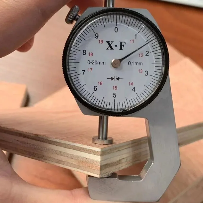
A dial gauge contacting the panel at its exposed edge during thickness measurement. Keep the selected measurement positions and condition with the order inspection record.
Use the stated panel range
The technical data specifies 9mm ±0.25mm, or 8.75–9.25mm before added coatings or adhesive. Define the finished fitting condition and measuring stage with the part drawing.
Check the deepest machining
Include the drill point, tool setting and depth variation when calculating the remaining local section. Mark both-face operations at their actual locations.
Review the core at the connection
Use the intended hole, pocket and exposed edge in a sample of the selected core. Carry the fitting’s material requirements and installed performance into the component trial.
For a selected 8.8mm section and 6.3mm maximum machining reach, the geometric remainder is 8.8 − 6.3 = 2.5mm. Using the technical-data lower limit of 8.75mm with the same tool depth gives 8.75 − 6.3 = 2.45mm. Choose the full thickness and machining limits with the hardware detail, then assess the fitting in that construction.
For through-fixings, include head, washer or bearing detail, opposite-face clearance and tightening access. For removable parts, review repeated handling and replacement with the actual hardware and support.
GRAIN DIRECTION · FINISHED SIZE · MACHINING ALLOWANCE
Compare final rectangles and oversize blanks on the sheet
This cutting comparison uses the 1220 × 2440mm format with 10mm trim at every edge and 3mm kerf, leaving 1200 × 2420mm. The three rows are separate component requirements with their own drawing and orientation.
Read the worked detail and calculations
Regular grids; first orientation keeps the longer part edge along the sheet length
Blank requirement
First orientation
Rotated orientation
What changes
600 × 900mm finished rectangle
1 × 2 = 2
1 × 4 = 4
Rotation changes the relationship of the face grain to the long part edge.
598 × 900mm finished rectangle
2 × 2 = 4
1 × 4 = 4
This is a different component width; it must satisfy its own drawing.
606 × 906mm oversize blank
1 × 2 = 2
1 × 3 = 3
A 3mm allowance on all edges of a 600 × 900mm part affects the layout.
Two 600mm widths and one kerf need 1203mm, beyond the 1200mm usable width. Two 598mm widths need 1199mm, leaving 1mm after the stated edge trim. Include the actual minimum sheet dimensions and any further machining allowance in the production layout.
Rotating the 600 × 900mm rectangle puts one 900mm edge across the sheet and four 600mm lengths along it: 4 × 600 + 3 × 3 = 2409mm. Four 606mm oversize lengths would need 2433mm, beyond 2420mm; three use 1824mm, yielding three rotated blanks.
Select 600mm finished width, 598mm finished width or 606mm oversize width according to the component drawing. Keep grain, matched-face direction and finishing allowance with that choice. Compare a mixed-part nest separately where the cutting list contains other sizes.
Allocate the outer blank before an internal offcut
A component with an opening still needs its full outside rectangle on the sheet. Assign an internal offcut to another part only where its dimensions, toolpath, tabs, appearance and handling condition fit that second requirement.
REQUIRED COMPONENTS · SUPPLIED STAGE · MATERIAL INPUT
Plan the order for 240 accepted components
For 240 outside rectangles at 600 × 900mm, the first orientation uses 120 sheets and the rotated route 60. Choose the route that matches the face grain, appearance and processing schedule.
240 pieces; 10mm sheet-edge trim and 3mm inter-part kerf
Accepted blank and orientation
Pieces per sheet
Sheets
Input sheet area
600 × 900mm · first orientation
2
120
357.216m²
600 × 900mm · rotated
4
60
178.608m²
606 × 906mm · rotated oversize route
3
80
238.144m²
The third row supplies a 3mm allowance on each edge of the final part, using 606 × 906mm blanks. This separate stage may suit trimming after another operation. Keep the supplied blank and completed drawing dimensions together in the quotation.
The 240 outside rectangles contain 129.6m². With the same 240 × 400mm opening in each, retained panel area totals 106.56m². Under the separate 15kg sheet budget, retained material is approximately 536.95kg; adding 0.50kg per component gives approximately 656.95kg for the 240 completed assemblies before packing.
At that same budget, 120, 60 and 80 uncut sheets represent 1800kg, 900kg and 1200kg of input material. Use the actual selected configuration and delivery stage for shipping mass, with the finished additions and protective packing recorded separately.
State the accepted part quantity, face range and supplied cutting allowance. We can include samples, agreed production allowance, useful offcuts and matched replacements in the order plan.
Carry the critical part details through the workshop sample
Read machining and workshop guidance
Machine the detailed opening
Include internal corners, smallest retained section and the last released cut. Use the intended tool, support and clamping sequence; review both faces and the exposed edge.
Where a grille or fitting covers the opening, trial its seating and hole pattern on the machined sample with the actual connection and surrounding support.
Define every edge treatment
Mark visible, banded, channel-fitted and concealed edges, including those inside the opening. Select the core appearance and finish for the surfaces buyers will see or touch.
Include added edging and removed preparation material in the final outside size. Locate the edge, mating parts and fixings from the same datum.
Develop the coating on the selected face
Choose colour, permitted repairs, veneer joints, grain direction and reverse treatment under the intended lighting. The technical configuration is fine sanded on both faces at 150–180 grit.
Plan additional preparation with the selected face-veneer allowance and coating system. Review local corners and machining under the same finish used for production.
Weigh and fit the completed part
Include handles, retainers, edging and permanent additions before weighing and fitting. Use the actual supports and clearances, and check the installation, operation and removal route.
Keep the drawing revision, panel identity, finish and hardware with the sample. Review an updated core, fitting or process against the same completed-part requirements.
For a bonded backing or reinforcement, specify the carrier, adhesive interface and assembly process. For wall or furniture linings, coordinate joints, backing and attachment positions with the installed panel layout.
CORE & BOND · HUMID OR EXTERIOR USE · CURRENT RECORDS
Choose the service configuration with the finished assembly
The technical data offers MUF Class 2 or phenolic WBP Class 3 bonding, with the selected humid-interior or exterior/marine-joinery duty. Dispatch moisture is 8–12%. Identify the chosen core, bond and service conditions together on the quotation.
The declared mechanical figures belong to the all-Okoume construction. Use the relevant product information for the selected poplar or eucalyptus option, and keep the specific bond and emissions requirements with its current documents.
For a marine, fire, structural or emission-controlled project, send the intended use, destination and required records. The Okoume marine plywood route provides a separately specified marine configuration for comparison.
Include humidity, cleaning, incidental wetting and exposed edges with the protection and joint details. For loaded components, add support, span, openings, connection, load distribution and duration so the construction and complete assembly can be reviewed for that duty.
FINISHED · WEIGHED · FITTED TO THE ASSEMBLY
Review one complete component with our factory
Prepare the selected 9mm core, face and bond with the intended cutting, edging and coating. Include the critical opening, retained sections and actual fittings, then place the part in its frame, support or receiving opening.
Review appearance, fit, finished mass, normal operation and removal against the same identified sample. Record attached items, material condition and weighing method, with any further load or durability assessment required for the assembly.
Our custom-size service links the sheet order to cut-part requirements. Send the sketch, dimensions, visible faces, openings, quantity and target weight where relevant. The factory team helps complete the configuration and supplied processing around those details.
MATERIAL IDENTITY · FINISHED COMPONENT · SUPPORTED PACKS
Carry the accepted part and its records into delivery
Record the reference sample, method and accepted limit
Checkpoint
Record
Connection to the finished part
Construction and identity
Face/back, selected core, layup, bond, order and pack identification.
Mass, machining and connection comparisons must refer to the same construction.
Dimensions and condition
Actual thickness, sheet or blank dimensions, squareness method and measuring condition.
Use accepted limits for the overlap, fitting depth and cutting plan.
Face and cut edge
Appearance range, repairs, grain direction, edge condition and machined opening.
Review the visible face, exposed core and internal corners together.
Mass
Dimensions, scale, condition and the exact weighing object with its included additions.
Distinguish a sheet reference from an accepted maximum for the completed part.
Fitting and finish
Hardware reference, actual hole geometry, coating, rear treatment and functional result.
Check the selected material in the actual assembly and removal route.
Packing
Counts, supported stack, face/edge protection, part orientation and labels.
Protect narrow sections around openings and prevent mix-ups in matched sets.
Support sheets flat and protect faces and edges from wetting or local damage. Pack components with large openings or narrow retained sections on supporting layers suited to their shape, keeping face orientation and matched groups identified.
The production and quality page outlines the factory and packing process. Retain the accepted component, material and hardware references for repeat work, with actual pack dimensions and gross mass for delivery planning.
Use the product enquiry form or email your sketch, drawing or sample reference to sales@plywoodsupplier.cn. Include quantities, destination and timing so we can quote the selected construction, processing and packing together.
PLAN YOUR PANEL ORDER
Bring the face, fit and finished handling weight together.
Work with our factory on the selected core, Okoume appearance, machined openings and delivered finish. We help turn the part drawing into a fitted sample, a clear weight brief and a quotation for the work you want supplied.
9mm Okoume Plywood
Your core, fitted component and finished-weight brief
Visible faces, core choice and finished-weight target
Part drawing, openings, overlap and fittings
Supplied finish, accepted quantities, packing and destination
Include the critical opening, actual edge treatment and intended hardware in the selected 9mm construction. Fit the finished part in its frame or opening and weigh it with every permanent addition, keeping the sample identity with the drawing.
Standard samples without special work or a logo have no sample charge; delivery is separate. Custom samples are agreed individually.
Order quantity
Our starting guidance is one container for standard sizes and 3,000–10,000 pieces for custom sizes or designs. Tell us your trial quantity.
Production
All products are made to customer order. Production takes 10–15 days; the order confirmation records the start date and production schedule. Sea transit is additional.
Payment
Where a deposit applies, our standard reference is 30% before production, with the balance after inspection and before loading. T/T or L/C terms are agreed for the order.
Shipping
Panel orders ship by container. Share your destination so we can arrange the loading plan and quote the freight separately from production.
After-sales warranty
All products include a 180-day after-sales warranty. Contact our team with the order reference and details of any product concern.
Tell us your quantity, sample needs and target delivery date. We’ll put the price, payment terms and production schedule into your quotation.
Share the material, thickness and test standard your project requires. Our factory team will help you select the product reports and documents for your purchase.
Production & inspection
We can plan production and inspection around your panel specification, with dimensional checks, recorded readings and packing photographs for your order.
We prepare packing details, pack quantities and dispatch documents for your order. Share the destination and receiving requirements so our team can help plan delivery.
Choose Okoume-faced plywood with an all-Okoume, poplar or eucalyptus core. The technical data lists density ranges of 500–540, 480–520 and 600–650kg/m³ respectively. Select the core with the part’s weight, cut edge, support and fittings, and keep that named construction with the sample and quotation.
Which sheet sizes and thickness limits apply?
The technical data lists 1220 × 2440, 1250 × 2500 and 1525 × 3050mm. At nominal 9mm, ±0.25mm gives 8.75–9.25mm. Send custom blank or part dimensions with any tighter limits, processing allowances and the finished stage at which the component needs to fit.
How much does a 9mm Okoume sheet weigh?
The named all-Okoume transport configuration uses 520kg/m³, 7 plies and 4.68kg/m²: about 13.9kg per 1220 × 2440mm sheet. The component calculations use a separate rounded 15kg sheet budget. Your quotation and pack follow the chosen construction, dimensions and delivered condition.
What is included in a finished-component weight target?
Include the retained panel, edging, cured coating, fittings and any backing, grille, gasket or reinforcement that stays attached. Define the weighing condition with the complete part. Packed shipping mass adds protection and pallets to the actual delivered contents.
How is a panel with an opening estimated?
A 600 × 900mm rectangle has 0.540m² area. A centred 240 × 400mm opening removes 0.096m², leaving 0.444m² with 180mm side borders and 250mm top and bottom borders. Using the 15kg sheet budget gives about 2.237kg of retained panel. Add the specified finish and hardware to plan the complete part.
How can I keep the finished part within its weight target?
For the stated opening, adding 0.32kg of fittings and 0.18kg of edging and cured finish gives about 2.737kg against a 2.80kg target, leaving about 63g. Weigh the actual finished sample with every permanent item, and carry the same construction and processing references into the order.
What changes when the sheet mass changes?
With the same 0.444m² retained area and 0.50kg additions, sheet-mass inputs of 14.4, 15.0 and 15.6kg give finished estimates of 2.648, 2.737 and 2.827kg. Use this comparison to set the material and weighing brief, then measure the selected finished component against its agreed maximum.
How do I specify a removable cover’s overlap?
A centred 600 × 900mm cover over a 560 × 860mm opening has 20mm overlap on each side. For selected component widths of 599.6 and 560.4mm, horizontal overlap is 19.6mm; a 1mm offset gives 18.6mm on one side and 20.6mm on the other. Define the actual panel and opening limits with the retainer, seal and datum.
How do I choose fittings and machining depths?
Send the fitting model and preparation instructions with both-face operations and the full tool geometry. For a selected 8.8mm component minimum and a 6.3mm deepest cut, 2.5mm remains. The TDS lower limit of 8.75mm would leave 2.45mm at that cut depth. Choose the required panel limits and review the complete connection in the selected core.
Can I use this panel for framed inserts or supported drawer parts?
Yes. Include the frame or channel, clear span, contents, support and fitting arrangement. We help choose the face, core and supplied work around that assembly. Review the opening, corners and connections with the required service performance as well as the finished appearance.
Why does grain direction affect the cutting quantity?
On a 1220 × 2440mm sheet with 10mm perimeter trim and 3mm kerf, 600 × 900mm rectangles fit two positions with the 900mm edge along the sheet length, or four when rotated. Keep the selected grain and face orientation with the actual part drawing before choosing the layout.
How do final size and trimming allowance change the layout?
Two 600mm widths plus one 3mm kerf need 1203mm, exceeding the 1200mm trimmed width. Two 598mm widths need 1199mm and belong to a separately accepted part size. Adding 3mm on every edge of a 600 × 900mm part produces a 606 × 906mm blank, giving three rotated positions per sheet.
How many sheets are needed for 240 components?
Under the stated regular-grid inputs, 240 finished-size 600 × 900mm rectangles need 120 sheets in the first orientation or 60 when rotated. The 606 × 906mm oversize route needs 80 sheets. Compare these routes with the accepted face areas, grain, processing allowances and actual supplied stage.
Which bond and product documents should I request?
Select the core and MUF Class 2 or phenolic WBP Class 3 bond around the exposure and project requirements. The technical performance figures describe the all-Okoume group. Include any marine, structural, fire or emissions requirement with the product records and configuration needed for your order.
What makes a useful sample for this product?
Use the selected core to make the component with its opening, edging, finish and actual fittings. Fit it in the receiving frame or opening, check the removal route, and weigh it with all permanent attachments. Retain the drawing revision, finish and hardware references for production.
What should I send for a factory quotation?
A drawing, sketch or component photo is enough to start. Add sizes, visible faces, openings, quantity and destination, with a finished-weight target where needed. We help complete the sample and supply scope. Available to order: 10–15 days production, container shipping, freight terms per order and 180-day after-sales warranty.
Share a sketch, furniture photo or drawing with the visible surfaces, openings and intended use. We help choose the core and sample route, then plan sheets, blanks or machined parts for your order.
Thickness limits: TDS-PS-06: ±0.25mm at 9mm, giving 8.75–9.25mm; identify any tighter component limits and supplied stage.
Face and reverse veneer: African Okoume / Gaboon (Aucoumea klaineana); 0.50–1.20mm veneer reference in the technical data.
Have a cover drawing, fitting reference or finished-weight brief? Email it to sales@plywoodsupplier.cn. Start with the details you have; we’ll help you work through the rest.
CONTINUE YOUR PANEL SELECTION
Okoume veneer plywood
Compare our panels
Browse the material range and compare the configurations for your order.
Optional Google Analytics and Ads cookies measure visits and enquiries. Reject keeps these cookies off; basic cookieless measurement continues. Enquiry details are never sent to Google. Privacy details.