
Formwork camber is a specified upward profile used to produce the intended concrete geometry. Its amount, shape and measurement stage come from the project documents. For the plywood facing, start with the beam or slab you are forming and an available sketch; we help choose panels and develop parts that suit the coordinated profile.
Compare film faced shuttering plywood for the concrete-contact face. Where the design specifies 18mm, consider 18mm concrete shuttering plywood with the required construction and directional properties.
Understand what the specified camber is intended to address
The project may require camber to account for anticipated structural deflection, while formwork setting also needs to address movement of the temporary supporting arrangement. Establish how those matters are treated in the design rather than adding separate allowances twice.
ACI 347R's formwork guidance identifies the required camber for structural deflection as information to be provided in the contract documents. It also distinguishes measurement at a defined stage, showing why a camber value needs more context than a dimension alone.
Intentional camber is different from random waviness in a plywood face. It is also different from prestressing a member. Our prestressing and plywood stiffness article discusses that separate mechanical concept.
Read the complete profile before setting levels
Identify the member, drawing revision, span definition, reference datum and required setting-out positions. Confirm whether the stated levels refer to the concrete soffit, the top of the facing or another reference surface. Those locations cannot be interchanged without accounting for the components between them.
A midspan rise alone may leave the profile between supports undefined. Obtain the specified shape or station levels, particularly for continuous members, cantilevers, variable-depth beams and two-way slabs. Do not apply a simple symmetric curve to a different structural arrangement without the designer's instruction.
Record the load state and measurement time associated with the target. A level before concrete placement and a level after the fresh concrete has loaded the form describe different conditions.
Separate global camber from local deformation
| Effect | What it describes | Information to resolve |
|---|---|---|
| Specified camber | An intentional profile along or across the member | Design profile, datum and measurement stage |
| Local facing deflection | Plywood bending between its immediate supports | Facing properties, orientation and support arrangement |
| Support movement | Displacement within the temporary load path | Beams, props, joints and bearing conditions |
| Specified slope | A deliberate fall or inclined surface | Level geometry coordinated with the camber profile |
Increasing a global camber allowance does not correct an unsupported plywood edge or a locally flexible facing. Likewise, a visible slope should not be “levelled out” if it is part of the specified geometry. Compare observations with the intended profile before classifying them as errors.
Treat plywood as one part of the supporting arrangement
The plywood transfers load into its immediate supports, which transfer it through the rest of the temporary structure. Its thickness, directional stiffness, joints and condition affect local response, but they cannot define the behaviour of the complete beam-and-prop arrangement.
Our plywood bending-stiffness guide explains why thickness and orientation need to be considered with span and loading. A nominal 18 mm panel should not inherit a support spacing or camber instruction from another panel construction without the relevant assessment.
UK HSE guidance on temporary works describes the need for suitable design and checking. In procurement, preserve the specified plywood properties and support assumptions when evaluating a proposed substitution.
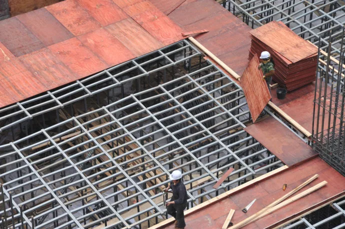
Translate a supplied profile into a level schedule
The following example illustrates arithmetic only. Assume a project drawing already specifies a constant reference soffit level of 10.000 m and upward offsets of 0 mm, 8 mm and 0 mm at the three listed stations. These assumed offsets are not recommended design values or a rule for a 6 m span.
| Station | Reference level | Specified upward offset | Target level |
|---|---|---|---|
| 0.0 m | 10.000 m | 0 mm | 10.000 m |
| 3.0 m | 10.000 m | +8 mm | 10.008 m |
| 6.0 m | 10.000 m | 0 mm | 10.000 m |
Here, target level equals reference level plus the upward offset expressed in metres. For a sloping reference, calculate from each station's own reference level. Add every setting-out station required by the actual drawing; three values alone do not define the entire curve between them.
Keep instrument readings separate from these target elevations. The survey method determines how readings are converted to levels, and both should remain traceable to the same benchmark.
Coordinate the soffit with thickness, cover and interfaces
Changing a soffit level while keeping another surface fixed can change the concrete depth. The camber detail therefore needs coordination with the top surface, reinforcement position, required cover and any varying section dimensions.
Review beam-to-slab junctions, openings, embedded items and transitions to adjacent work. A profile that appears clear in a single section may conflict with another member or with a required finished level. Resolve those interfaces on coordinated drawings before adjusting the form.
For work specified under the European framework, EN 13670 concerns execution of concrete structures. Use the applicable project specification and execution requirements to establish tolerances and inspection records; its title alone supplies no universal camber value.
Check the defined profile at the defined stage
Prepare a record containing member identification, drawing revision, station, target level, observed level, deviation, date and loading condition. The timing matters because comparing an unloaded measurement with a loaded target can produce a misleading result.
Check before placement as required by the inspection plan, and record later measurements at the prescribed stages. ACI 347R discusses measuring attained camber at the soffit after initial set and before support removal. That reference does not eliminate the need for the project's setting-out and acceptance checks.
If a measurement falls outside the agreed criteria, document the location and refer it for the specified corrective decision. Adjustments to loaded supports or changes during a pour are not routine survey corrections. Preserve the revised instruction with the subsequent check record.
Plan your plywood facing order
Start with the beam or slab use and an available section. We help choose the plywood construction and develop a sample around the relevant face, edge or joint.
Before production, agree the facing layout, dimensions, quantities, material properties, finish and destination. Keep shaped edges, openings and joints connected to the current formwork drawing. The supplied profile and support design establish the geometry; the factory order records the matching panel details and tolerances.
Beam and slab plywood facings buying questions
Does 18mm plywood determine the camber?
No. Camber comes from the project profile and specified measurement stage. Panel thickness, construction and direction affect the local facing response.
What should a facing sample help us check?
Use it to review thickness, construction, surface and a representative shaped or joint detail. The project design and survey checks address the complete profile.