
Choose a panel and fastening detail together for hinges, shelf supports and furniture joints. Plywood, MDF, particleboard and OSB engage nails and screws differently; the fastener, insertion position and load determine the useful comparison. We manufacture plywood and MDF in our own factory and help develop the panel, drilling and joint sample for your component.
Start with the furniture idea, a photo of the fitting or a drawing. Our melamine-faced plywood and furniture melamine MDF give two product routes to compare around the same connection.
Melamine-faced plywood Furniture melamine MDF Plain MDF
Identify the action at the connection
| Action | What happens | What must be assessed |
|---|---|---|
| Axial withdrawal | The fastener is pulled back along its axis | Engagement of the shank or thread with the substrate |
| Lateral loading | The connected parts tend to slide across the fastener | Fastener bending, material bearing and the complete joint |
| Head pull-through | The head or washer is pulled through the attached panel | Head geometry, local panel condition and attachment detail |
| Combined action | A bracket or fitting applies more than one action | Load path, geometry and relevant connection interaction |
The US Forest Service Wood Handbook chapter on fastenings treats fastening types and loading modes separately and relates connections to material properties and moisture change. The practical point is to use a joint design suited to the action. A test force for a single fastener is not automatically an allowable load for an assembled cabinet or building detail.
Show whether the fastener enters a face or edge
A face fixing enters through the broad surface of the panel. An edge fixing enters through its narrow thickness edge. These descriptions are clearer than across the layers when a drawing is absent. Show the fastener axis and panel faces on the detail when discussing a test or an order.
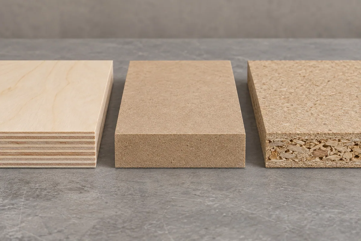
In plywood, a face fixing passes through successive veneers, while an edge fixing engages a local combination of veneers and bond lines. Gaps, repairs and lay-up can affect that local material. Cross-lamination does not make plywood isotropic or guarantee that every edge position will perform equally.
MDF and particleboard also need separate face and edge evaluation. Their structure through the thickness can differ from the surface region. Do not assume that a favourable face test also covers a narrow edge joint.
Compare the construction around the fixing
| Material | Relevant construction details | Comparison to request |
|---|---|---|
| Plywood | Species and veneer lay-up, local gaps, thickness and grade | Specified fixing in the intended face or edge position |
| MDF | Grade, density profile, thickness and machined condition | Suitable screw and pilot-hole arrangement for that board |
| Particleboard | Grade, face and core structure, local consolidation | Hardware designed for the substrate and intended assembly cycle |
| OSB | Grade, strand arrangement, thickness and direction | Applicable panel and connection evidence for the use |
| Solid wood | Species, grain direction, moisture and splitting risk | Relevant side-grain or end-grain connection detail |
Compare grades using the same fastener, insertion depth and position. That gives the construction table a practical purpose: choosing the detail to trial for your hinge, connector or bracket.
Choose the screw or nail with the hardware
Record the type, overall diameter, thread or shank form, thread length, head and point. A smooth nail, ring-shank nail and screw should not be treated as interchangeable test specimens. For a screw, the outer thread diameter differs from its core diameter, which matters when selecting a pilot hole.
Use the hardware system’s specified fastener for hinges, cam fittings and brackets. Check length and diameter with the fitting thickness, remaining board and seating detail before changing the screw.
The European Panel Federation's MDF screw guidance discusses screw geometry, pilot holes and fixing position. It also notes that holding comparisons depend on using the same screw type and test method. Use its board-specific guidance with the hardware instructions rather than copying one drilling diameter to every panel and screw.
Check engagement and remaining material
Overall screw length is not the same as effective engagement in the board. The fitting thickness, unthreaded shank, point and installation geometry can affect how much thread engages useful substrate. Draw the assembled section to check both engagement and whether the screw could break through the opposite face.
In an edge joint, the fastener must also remain correctly positioned within the board thickness. A hole drilled off-centre can leave much less material on one side. If the component is thin, choosing a larger screw may increase splitting or breakthrough risk instead of providing the desired improvement.
Use the relevant material and hardware guidance to set edge distances, hole depth and clearances. There is no single minimum edge distance that is valid for all of these materials and fastener sizes. For construction connections, follow the applicable engineered detail and product evidence.
Drill and tighten without damaging the joint
Inspect the hole location, depth and condition before assembly. A damaged entry, incorrect pilot or blunt drilling tool can make a good material appear unreliable. Keep the part supported and aligned so the fastener does not force a misaligned joint into place.
Use the specified installation method and tightening control. Excess torque can strip the material or crush the region beneath the head. A screw that rotates without developing the intended seating condition needs investigation; repeated tightening does not recreate the lost substrate.
Record when a failure occurs. Splitting during installation, loosening after assembly and failure during a load test are different observations. Compare the material and hardware details with the drawing before assigning the cause to the board family.
Compare withdrawal tests on the same basis
EN 320:2011 specifies axial screw-withdrawal testing for particleboards and fibreboards. Do not label a plywood or whole-furniture result as equivalent merely because it is also reported in newtons. Select the applicable method for the material and question being tested.
For a useful comparison, retain the board grade, thickness, conditioning, specimen count, face or edge position, screw specification and insertion details. Read the individual results and the prescribed summary. Failure force, a statistical characteristic value and a design resistance are distinct quantities.
As a reporting example, 1.2 kN equals 1,200 N. That unit conversion does not make a result comparable with a 1,000 N test performed using a different screw or load direction. Nor should it be converted directly into a safe shelf weight: the assembled load path, number and arrangement of fixings and design requirements still matter.
Try the complete fitting and repeated use
A hinge can apply leverage and repeated movement that a single axial pull test does not represent. A shelf support, drawer runner and wall bracket have other geometries. Evaluate the specified fitting on a representative component, with the load and cycling relevant to the product.
If furniture is designed for repeated assembly, specify that requirement early. Reusing the same hole can change its condition. A connector or insert intended for repeated use may be appropriate, but its performance still depends on the substrate, installation and test. Adding an insert is not an automatic repair for an already damaged core.
For plywood edge appearance and cabinet construction, see our plywood–particleboard comparison. It connects the fastening choice with the rest of the component specification.
Check connections affected by moisture or damage
Check moisture exposure, corrosion suitability and local substrate condition where the connection will be used. A fixed test result on conditioned specimens should not be treated as proof of performance after swelling, splitting or repeated wetting. Surface coating alone does not protect every fastener entry.
If a load-bearing fitting has loosened because the surrounding board is damaged, address the damaged material and connection design. Filling a visible hole or driving a screw nearby is not evidence that the original load capacity has been restored. Our crack-prevention guide helps distinguish surface appearance from core damage.
Develop the panel order around the joint
Start with a fitting photo, component sketch or drawing through our enquiry form. We help compare melamine-faced plywood and furniture melamine MDF around the joint. Add thickness, fixing location, expected load, assembly cycles and use conditions as the detail develops; include any required test method with the sample plan.
Panel fixing questions
Which holds screws better: plywood or MDF?
Compare the actual constructions with the same screw, insertion depth, face or edge location and test method. The best choice for a hinge or connector also depends on drilling, component geometry and repeated use.
Can a withdrawal result be used as a shelf load rating?
A withdrawal result describes its defined test. A shelf also depends on support spacing, panel bending, fitting geometry and the complete load path, which need their own design assessment.
What should I send if the hardware is not selected yet?
Start with the furniture use and a photo or sketch of the joint. We help develop the board choice and machining brief; the selected fitting instructions guide the final drilling and sample.