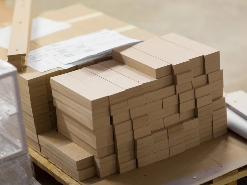
Your part list. MDF ready for the next workshop operation.
Start with the MDF parts your workshop needs: rough blanks, cut-to-size substrates or machined components. We manufacture MDF in our own factory in Jiangsu, China and bring your cutting list, drawing revisions and packing groups into a coordinated production order.
Available to order · 7–10 day production cycle. Choose the delivered stage and included processing in your quotation.
CUT SIZES, MACHINED FEATURES & A DEFINED DELIVERY
Receive the MDF parts your next station needs.
Receive custom-size raw MDF ready for the next stage of your furniture, joinery or interior project. Start with the part your workshop needs, then connect the substrate, delivered size and requested operations in one cutting list. Our team helps turn that schedule into a clear production quotation.
We manufacture MDF substrates in our own factory in Xuzhou, China. Bring a repeating furniture component or a mixed project schedule, with drawings for features beyond straight cutting. We help develop the board, first-part set, processing and packing around the pieces your workshop wants to receive.
Choose the delivered stage for your component
Supply stage
What the size describes
What to include in the enquiry
Oversize raw blank
Material supplied with an agreed allowance for later sizing or profiling
Allowance on each edge, holding requirements and the final shape
Cut-to-size substrate
The raw component at its agreed cut or machined perimeter
Outside limits, squareness, surface condition and downstream edge treatment
Specified machined part
A component with the specified holes, grooves, rebates or profiles
Feature drawing, datum, machining side, depth, revision and acceptance checks
Build the quotation around the work you want included: straight cutting, holes, grooves, profiles, edge preparation and packing. Keep the raw supply stage clear and describe any paint, veneer or melamine required through the appropriate finishing route, so the delivered part matches your next operation.
Save receiving and sorting work with a part-coded order
Save time at receiving with parts identified by code, counted to your schedule and grouped for the next production station. Compare custom components with full-sheet supply around your complete workshop workflow, including cutting, sorting, processing and delivery.
Explore our Plain MDF page to develop the substrate, painting and routing detail. Use this custom-size route to bring that board into a part-coded drawing, cutting schedule and packing plan for the order you want to place.
CONSTRUCTION & SUPPLY CONDITION
Custom-size Raw MDF specification
Our product configuration and order requirements
Supply scope
Custom-size unfaced MDF blanks; additional machining or finishing quoted separately
Part schedule
Part code, dimensions, thickness, quantity, drawing revision and packing group
Common base format
1220 × 2440mm; thickness range 2.5–30mm
Further formats
1830 × 2440mm at 2.5–25mm; 1830 × 3660mm at 16mm
Large-format enquiries
2440 × 3660mm is listed; confirm thickness and availability for the order
Custom-size definition
State whether each size is an oversize blank, machined substrate or finished component
Wood-fibre references
Poplar, hardwood and pine; confirm the selected substrate configuration
Density and moisture references
700–900kg/m³ density; 4–9% moisture content; confirm the selected board and measurement stage
Internal-bond reference
>0.55MPa in our product data; applicable test and thickness to be confirmed
Bending-stiffness reference
Modulus of elasticity >3700MPa in our product data; not a component load rating
Water-absorption reference
≤10% listed; agree test method and duration, separately from thickness swelling
Emission requirements
E1/E2/E0/CARB references; identify the required scheme, method and applicable documents
Service conditions
Specify dry, humid or other exposure and the required board grade
Dimensions and tolerances
Agree individual limits for thickness, outside size, squareness, flatness and feature positions
Drawing references
Units, named face, datum edges, hole depth, edge profiles and revision
Machining scope
Straight cutting, holes, rebates, grooves and profiles are separate operations to define
Edges and subsequent finishing
Show retained edging, trimming and coating allowances at the appropriate stage
Rotation and handed parts
State permitted rotation; identify left/right versions and the view used on drawings
Samples and acceptance
Check representative critical parts and mating pieces against the agreed drawing
Packing and identification
Part-code quantities, group labels, protection, pack dimensions and actual gross weight
Choose the construction, finish and size for your project. We’ll bring the selected options and finished tolerances together in your quotation.
COMPONENT ORDERS WITH DIFFERENT ACCEPTANCE PRIORITIES
Find your custom MDF route for furniture and interiors
Furniture-production blanks
Start furniture production from repeat part codes, counted quantities and the raw sizes your next station needs. Include the following groove or edge process, grouping the pieces for receiving with the board identity and selected machining reference.
Painted fronts and routed decorative parts
Develop painted fronts with face profiles, reverse pockets and final edges shown together. Carry a useful part through the coating preparation and finish, reviewing profile definition and the fit your customer will use.
Interior trims and narrow mouldings
Bring the moulding cross-section, length, end detail and intended joints. Identify visible edges and handling supports, planning protection for long narrow pieces around their shape and receiving process.
Veneering and laminating blanks
Choose whether veneer or laminate facing comes before or after final cutting. Include press allowance, balancing reverse, final thickness and decor direction, with labels placed clear of surfaces entering the bonding process.
Display and assembly kits
Plan display kits around the complete assembly, including handed pieces, mating connections and repeated use. Use matching codes and quantities to make components easy to locate, reviewing the selected substrate and hardware for their required joint duty.
Templates and packaging components
Bring the locating holes, contours, contents or contact surfaces for a template or packaging component. Include wear, load and operating conditions with the dimension brief so the substrate and inspection checks follow the job the part will perform.
Bring flooring, structural, waterproof or fireproof project requirements with the intended construction. Our team helps select the substrate grade and relevant documents alongside the custom dimensions and processing needed for that duty.
BASE MATERIAL, FINISHED SIZE & TOLERANCE BUDGET
Connect the board grade to the part you need
Our base sizes are 1220 × 2440mm at 2.5–30mm, 1830 × 2440mm at 2.5–25mm and 1830 × 3660mm at 16mm. We also list 2440 × 3660mm, with thickness to be agreed. Select the base format, thickness and grade together; we’ll use your part schedule to plan the sheet allocation and delivered dimensions.
Our range gives poplar, hardwood and pine fibre references, density of 700–900kg/m³ and moisture content of 4–9%. We identify the selected substrate in the order. A dimensionally correct blank still needs the right surface, machining behaviour and service grade for the component you intend to make.
Carry performance requirements into the selected thickness
The material-property references include internal bond >0.55MPa, modulus of elasticity >3700MPa and water absorption ≤10%. Your order specification connects those properties with the selected thickness, test method and acceptance limits. Include thickness swelling separately when required and use the component design for shelf loads and support spacing.
Choose the service grade for the room and the emission requirement for the destination. Send the requested E1, E2, E0 or CARB scheme and document checklist with your part schedule, so the selected MDF and its supporting records follow the intended use.
The European Panel Federation’s MDF property guide explains the distinctions between density, internal bond, bending and thickness-swelling measurements. We use product-specific evidence and agreed limits for our quoted supply.
Open the blank-size, edging and tolerance worksheet
Work backwards from a finished perimeter
For the cutting worksheet below, start with a 600 × 740mm finished component. Use a retained edge build of 2mm on the left and right, and 1mm on the top and bottom. These inputs include the net edging and retained glue after finishing; use the actual net additions for your own component.
The substrate ready for edging is therefore 596 × 738mm. If your workshop needs 3mm final-sizing allowance at each substrate edge, the rough blank becomes 602 × 744mm. The example does not include a further dimensional change from coating. Add any such change at its actual process stage.
Blank, substrate and finished dimensions for the 600 × 740mm component
Stage
Width × height
Reason for the difference
Rough blank
602 × 744mm
Includes 3mm to remove from each substrate edge
Substrate ready for edging
596 × 738mm
The dimensions after final sizing and before edge additions
Edged perimeter
600 × 740mm
Adds 2mm per side and 1mm per end
Sending only “600 × 740mm MDF” leaves all three stages open to interpretation. Mark the required delivered stage on the cutting list and show any downstream operation that affects it. For an irregular part, distinguish its rectangular blank from the final contour and include the material needed for workholding.
Allocate tolerance across the whole dimension chain
For a finished-width requirement of 600.0 ±0.3mm, work backwards through the cutting and edging operations. If the substrate is 596.0 ±0.2mm and each retained side edge is 2.0 ±0.1mm, worst-case addition gives a finished range of 599.6–600.4mm. That does not fit the requested 599.7–600.3mm interval even though the centre dimensions add correctly.
With the same edge-build inputs, a substrate of 596.0 ±0.1mm gives 599.7–600.3mm. That uses the entire tolerance budget. Include any later dimensional change before setting the cutting limits, then agree the production tolerance for the actual board, part and measurement stage.
Choose outside-size, squareness, flatness, thickness and feature-position limits around the actual part and its measurement condition. Include the receiving opening for a fitted rectangle so the quoted dimensions and geometry describe the complete assembly requirement.
NAMED FACE, REFERENCE EDGES & HANDED COMPONENTS
Keep the drawing face and handed parts clear
Name the face shown on the drawing, define the origin and identify the physical datum edges used during machining. Keep those references visible when a part is turned over. A clear edge and face reference lets our team quote, machine and inspect the same feature.
Open left/right drawings and coordinate conversions
Continue the 600 × 740mm finished-perimeter example above. View both parts from the same named face F, with the finished left edge as x = 0 and the finished bottom edge as y = 0. The left version has feature centres at x = 37mm, while its mirrored right version has them at x = 563mm. Both have y positions of 100 and 640mm.
The drawings below locate feature centres. Add diameter, depth, machining side and the fitting reference to turn those centre positions into the production instruction.
A named face and datumMark the view and origin before adding machining side, diameter, depth and tolerances. The circles locate centres only.A separate handed identityMirror the x positions in this face view. Do not assume that turning the left part over reproduces its drilling side or other features.
Translate the coordinates when the reference edge changes
The substrate’s left and bottom edges sit 2mm and 1mm inside the finished perimeter. The rough blank extends 3mm beyond each substrate edge. Consequently, the lower left-version centre is (37, 100) from the finished origin, (35, 99) from the substrate origin and (38, 102) from the blank origin.
Centre coordinates in millimetres, viewed from the same named face
Feature
Finished origin
Substrate origin
Rough-blank origin
Left version · lower
37, 100
35, 99
38, 102
Left version · upper
37, 640
35, 639
38, 642
Right version · lower
563, 100
561, 99
564, 102
Right version · upper
563, 640
561, 639
564, 642
The two vertical positions are 540mm apart at all three stages. Their distance from an outside edge changes because the edge changes; the feature-to-feature distance does not. We retain both relationships when checking the drawing instead of independently copying coordinates between stages.
Mirroring and turning over are different instructions
Show each handed component from the named drawing face, including blind-hole access and visible recesses. Give left and right versions their own code or handed suffix so the machining side and orientation stay clear through production and assembly.
Allow rotation for symmetric raw rectangles where your process permits it. Keep drilling, face designations and later directional finishes with the part identity, using clear labels for pieces that share an outside size but need different features.
Use one drawing for quoting, machining and inspection
Send a dimensioned drawing with units, overall dimensions, thickness, feature sizes, depths, datums and revision. Keep any CAD file aligned with that drawing and name the controlling reference. Our team helps review a usable file format and the dimensions needed to quote and inspect the part.
Include the receiving component or hardware reference where parts mate. Mark critical relationships such as a hole pair locating a fitting, so the first-part review checks the assembled fit alongside each coordinate.
CUTTING, ROUTING, EDGES & DOWNSTREAM FINISHING
Choose the cutting and machining you want included
Straight cuts and final perimeter
Choose the cut size and identify which edges are final, exposed or left for later trimming. Include squareness and the intended fit. Plan holding or profiling allowance for a rough blank and the completed perimeter limits for a part supplied ready for assembly.
Holes and reverse operations
Show through or blind holes with diameter, depth, machining side and position. Include the deepest tool reach and review operations approaching from opposite faces together, keeping the required material section visible in the part drawing.
Rebates, grooves and profiles
Describe grooves, rebates and profiles with widths, depths, start and stop positions and a useful cross-section. Mark internal corners and surfaces visible after finishing, with fixture or holding allowance identified separately from the completed contour.
Edge preparation and facing
Choose a raw cut component, a surface prepared for your finishing process or an agreed added facing. Identify edges for banding, bonding or painting, carrying final rounding and flushing into the delivered-size and finished-size plan.
Read routing, surface preparation and decorative supply options
Evaluate the actual routed detail
Develop the machining trial around the deepest cut, narrow retained feature and a representative corner. Review the raw result through the intended preparation and finish, keeping profile definition, appearance and final dimensions together.
Plan tooling, feed and material removal around the selected MDF and component. Where roughing and finishing passes are useful, review their resulting surface and dimensions on the first part and retain the selected process with the order.
The European Panel Federation’s profiling guide explains the relationship between tooling, feed and finished cut quality. Use the selected board and actual profile to agree the tooling process and acceptance limits for your order.
Choose raw components or a decorative supply route
Choose a decorative supply route when your component needs white, black, yellow, red, beech, cherry, maple, pine or teak melamine decor. Specify the decor code, texture, face and reverse construction and edge treatment alongside the custom dimensions, with raw MDF kept as the unfaced option.
Tell us which preparation your workshop needs before coating or veneering a raw blank. For machined components, identify the features completed before dispatch and those your workshop will finish, including edging, drilling after edging and final calibration.
Settle the feature most likely to delay your assembly with a useful first-part set. Include the critical recess, blind connector or mating piece alongside the outside dimensions and labels, giving the trial the same demanding detail as your production component.
Use the following cutting worksheet for 20 sets of furniture-production blanks. It follows a separate part schedule from the edged component above, with quantities grouped by code and thickness. Add your own joints, final trimming and trial pieces when developing the production schedule.
Open the 20-kit cutting, volume and weight worksheet
One part code per size and thickness
Part code
Blank dimensions
Per kit
For 20 kits
S · side blank
720 × 360 × 18mm
2
40
H · horizontal blank
560 × 360 × 18mm
3
60
B · back blank
720 × 600 × 6mm
1
20
The order contains 120 blanks, not 20 individual panels. The 18mm and 6mm material must be allocated separately. We also keep sample pieces, agreed spares and replacements separate from the production quantity so the customer can see which quantities complete the required sets.
Use a stated usable rectangle and separation allowance
For this layout, use 1220 × 2440mm base sheets with 10mm trimming at each sheet edge. The usable rectangle is 1200 × 2420mm. Allow 3mm kerf between neighbouring blanks or strips. Rotation is permitted in this raw-blank example, and no additional fixture stock is included.
For the 18mm parts, three strips 360mm wide occupy 1086mm, including two separating kerfs. Along a strip, three S blanks occupy 2166mm; four H blanks occupy 2249mm; and one S plus three H occupy 2409mm. Each fits inside the 2420mm usable length.
The last pattern has only 11mm spare in that length. If the assumed usable length fell to 2408mm, the same pattern would no longer fit. Cutting plans should therefore use the accepted minimum usable size and actual process allowances, not only a nominal sheet label.
Four sheet patterns that together supply the 18mm part counts
Pattern
Three-strip arrangement
Parts per sheet
Sheets used
A
Each strip: 3 S
9 S; 0 H
2
B
Two strips: 3 S each; one strip: 1 S + 3 H
7 S; 3 H
1
C
Each strip: 1 S + 3 H
3 S; 9 H
5
D
Each strip: 4 H
0 S; 12 H
1
The plan uses nine 18mm sheets. It produces S = 2 × 9 + 1 × 7 + 5 × 3 = 40, and H = 1 × 3 + 5 × 9 + 1 × 12 = 60. Counts match the schedule without calling unmatched extra parts complete kits.
If S and H are cut only in separate uniform grids, S gives nine per sheet and needs five sheets; H gives twelve per sheet and needs five sheets. That comparison uses ten 18mm sheets. Within these two layouts, the mixed plan saves one sheet. The production layout also accounts for the accepted usable size, tooling and any additional workholding stock.
Allocate the 6mm backs independently
Two 600mm widths plus a 3mm kerf need 1203mm, so they do not fit across the assumed 1200mm usable width. Rotating the 720 × 600mm back blank allows one 720mm-wide column with four parts along the sheet: 4 × 600 + 3 × 3 = 2409mm.
That supplies four B blanks per 6mm sheet, so twenty require five sheets. The illustrated order therefore uses 14 base sheets: nine at 18mm and five at 6mm. Extra 18mm material does not offset a missing 6mm back; the thickness is part of the part identity.
Distinguish material bought for cutting from parts sent to the customer
Nominal material accounting for the worked 20-kit order
Material group
Base-sheet input
Required blanks
Blank material volume
18mm · S and H
9 sheets; 26.7912m²
100; 22.4640m²
0.404352m³
6mm · B
5 sheets; 14.8840m²
20; 8.6400m²
0.051840m³
Total
14 sheets; 41.6752m²
120; 31.1040m²
0.456192m³
Base-sheet volume is 0.5715456m³, while the scheduled blanks total 0.456192m³. Keep that input-to-delivery difference visible when comparing material allocations. Identify any useful remaining pieces you want retained or supplied separately from the scheduled blanks.
Using the listed 700–900kg/m³ density range gives a calculated net material weight of approximately 319.3–410.6kg for the 120 bare blanks. That is distinct from the weight of all input sheets and from shipping gross weight. We confirm actual packs and weights for the selected board and supply scope.
Receive the pieces in the order your team will use them: by part code for a production station, by assembly for kit building or by project area for staged work. Bring that preference with the order so quantities, pack lists and physical protection support your receiving process.
Separate an assembly group from a physical crate
For the twenty-kit example, four groups of five kits each contain 10 S, 15 H and 5 B, or 30 blanks per group. Each group contains 0.114048m³ of nominal bare-board material. Use that group reference across the physical packs, with pack size and weight arranged for support and unloading.
Plan physical packs around component dimensions, weight, support and unloading. Keep thin backs protected alongside thicker pieces, with a group-to-pack list connecting matching components where an assembly group spans several packs.
A useful component label
Part S · 720 × 360 × 18mm · Revision R2 · Raw blank · Quantity 10 · Group K01–K05
For this cutting worksheet, add the order and pack references, named face or handed suffix to the label. Keep its position clear of surfaces that will be bonded or finished.
Protect the actual shapes
Support small and narrow parts across gaps in a mixed stack, protecting corners and profiled edges. Identify fragile lands, finished faces and labels that your receiving team needs to reach, so protection and access follow the actual shapes.
Plan moisture protection, edge protection and load support with the pack footprint, gross weight and unloading method. Include support for long narrow blanks and destination details so the shipment arrives ready for your receiving arrangements.
Make changes traceable by part code
Keep a changed hole or profile traceable even when the outside size stays the same. Update the affected part code or revision, drawing, quantity and packing identity, retaining the definitions for parts whose requirements are unchanged.
Send the affected codes and the old and new requirements with each drawing change. Tell us whether earlier supplied parts must mate with the revision; our team reconciles the quotation, first-part checks, pack information and production timing around that change.
Keep offcuts, sample parts and spares separate
List useful spares by part code and revision, alongside the quantities needed to complete the assemblies. For retained offcuts, identify the minimum dimensions and intended use so suitable remaining pieces can be planned separately from sample and production parts.
Orders ship by container. Agree the pack footprint, loading arrangement, destination and freight terms for the actual component schedule, with a group-to-pack list for sets spread across different packs.
Keep the selected substrate, current drawing and cutting schedule with the supply. Identify the inspected part, revision and pack, connecting material documents to the board and feature checks to the delivered component so your receiving team has the right records.
Acceptance checks tied to the delivered scope
Item
Check
Retain with the order
Part identity
Code, revision, thickness, named face and handed version
Current schedule and matching drawing
Outside geometry
Length, width, thickness, squareness and flatness at the agreed stage
Limits, measuring method, condition and sample positions
Machined features
Diameter, depth, location, start/stop positions and machining side
Datum reference and critical feature results
Surface and edges
Cut quality, profile definition and condition for the next operation
Accepted raw or finished reference as applicable
Mating components
Relevant fit, handed pair or connector assembly
Actual mating-part and hardware references
Quantity and packing
Count by code, revision, group and physical pack
Reconciled pack list, labels and separately listed spares
Use an agreed measuring arrangement
Set the supports for flatness checks, thickness reading positions and feature datums with the drawing. Include a mating component or agreed gauge for close-fitting assemblies so the inspection review follows the same fit your workshop needs.
Define outside size and squareness independently, including the measurement condition and any diagonal check. Keep the required limits visible on the drawing and inspection plan so each characteristic has a clear acceptance reference.
Retain a representative sample through the production handoff
Retain the inspected part configuration and supplied process stage for repeat orders. Include a handed pair or mating set where useful, recording the number of pieces checked, acceptance basis and handling of parts needing correction with the production order.
Store the custom pieces without losing shape or identity
Store custom MDF dry, flat and supported off the floor, with aligned supports through stacked packs. Protect projecting corners and support short pieces across their footprint, keeping labels and component groups identifiable as the workshop opens each pack.
The European Panel Federation’s storage guidance explains the role of flat support and handling in retaining MDF condition. We agree protection and pack details around the actual custom shapes.
Our range lists 4–9% moisture content. Agree its measurement method and stage, and assess material condition before precision machining or bonding after delivery. Thickness and dimensions should be compared under the agreed conditions, particularly when transport and workshop environments differ.
Connect the board records to the parts in the pack.
Use the selected MDF grade and thickness as the material reference, the part code and drawing revision as the machining reference, and the accepted first-part set as the assembly reference. Connect those to the production order, lot and pack labels so purchasing and receiving can find the same configuration.
Start with one row per part code and revision, keeping dimension order and units consistent. State whether quantities are pieces, pairs or kits; include the pieces in each kit so the quotation, production count and receiving list follow the same schedule.
Material and dimension information
Bring the MDF grade, thickness, service conditions, delivered-size stage and limits you need. Include material properties and documents, with later trimming, edging or facing shown where it changes the completed dimensions.
Feature and delivery information
Attach the drawing face, datums, holes, profiles and revision to the part-code quantities. Add pack grouping, labels, destination and timing, identifying the factory processing and the operations your workshop will complete.
Settle the critical fit with a first-part set
Choose a first-part set around the detail you need to settle: the longest fitted component and receiving piece, critical hole and handed counterpart, or deepest profile through its intended finish. Review that relationship before repeating the production component.
Keep the first-part code, revision, material and process stage with the order. When a drawing changes, review which accepted features remain applicable and which need another check, recording sample pieces separately from the agreed production quantities.
Develop the broader processing scope through our custom dimensions and machining service, then bring the actual part schedule through the enquiry below or email sales@plywoodsupplier.cn. Our team helps turn your sizes, material and included operations into a coordinated quotation.
PLAN YOUR PANEL ORDER
Choose the part. Check the fit. Plan repeat supply.
Use the same material, drawing and first-part references from the quotation to the pack label. We help turn the cutting list into parts your team can identify and use.
Custom-size Raw MDF
Our MDF substrate production. We manufacture MDF substrates in our own factory in Jiangsu, China. Talk to our factory team about the board and finish for your components.
Connect your part schedule to the supplied MDF
MDF grade, thickness, delivered sizes and quantities
Part codes, drawing revision, datums and included machining
First-part checks, packing groups, destination and timing
Settle the critical fit with a first-part set: the required sizes, holes or profiles together with their mating pieces. Review the drawing face, finishing allowance and labels, keeping that reference with the production cutting list.
Standard samples without special work or a logo have no sample charge; delivery is separate. Custom samples are agreed individually.
Order quantity
The minimum MDF order is 1 × 20′ GP container.
Production
All products are made to customer order. Production takes 7–10 days; the order confirmation records the start date and production schedule. Sea transit is additional.
Payment
Where a deposit applies, our standard reference is 30% before production, with the balance after inspection and before loading. T/T or L/C terms are agreed for the order.
Shipping
Panel orders ship by container. Share your destination so we can arrange the loading plan and quote the freight separately from production.
After-sales warranty
All products include a 180-day after-sales warranty. Contact our team with the order reference and details of any product concern.
Tell us your quantity, sample needs and target delivery date. We’ll put the price, payment terms and production schedule into your quotation.
Selected MDF grade, thickness, base format, intended use and material documents.
Custom component
Part code, drawing revision, named face, machining datums, delivered dimensions and included processing.
First-part reference
Accepted component or handed pair, mating fit, finishing allowance and dimensional checks.
Order and shipment
Production order and lot, part quantities, packing groups and pack labels linked to the same drawing revision.
Product reports for your order
Share the material, thickness and test standard your project requires. Our factory team will help you select the product reports and documents for your purchase.
Production & inspection
We can plan production and inspection around your panel specification, with dimensional checks, recorded readings and packing photographs for your order.
We prepare packing details, pack quantities and dispatch documents for your order. Share the destination and receiving requirements so our team can help plan delivery.
A useful custom MDF offer connects the material allocation with the parts and operations being delivered. Send the part schedule and packing groups, and compare suppliers on the same delivered stage.
Agree the quotation basis for your custom MDF parts
Quotation item
What the offer should identify
Material quantity
The MDF grade, thickness and chosen basis: allocated base sheets or delivered part volume, as agreed in the quotation. Keep offcuts, trial pieces and spares identified separately.
Processing scope
The straight cuts, holes, grooves, profiles and surface preparation included, with any further finishing your workshop will carry out.
Part or kit price
The same part codes, drawing revision and quantities per kit. Use the complete quoted work to compare a price per component or assembly set.
Samples, packing & freight
Identify the first-part work and packing included in the offer, together with the separately stated charges, destination and shipping terms.
In the cutting worksheet above, 0.5715456m³ of base sheets supplies 0.456192m³ of scheduled blanks. Those are different quantity bases for the same layout. Ask for the selected basis and included operations in the offer before converting a board-volume price into a component or kit cost.
Available to order with a 7–10 day production cycle. We arrange container shipping and freight terms for your order; the sea transit schedule is separate from production. Our after-sales warranty is 180 days. If an issue arises, contact us with the order, part and pack references so we can agree the return or replacement solution and freight arrangements with you.
PRODUCT-SPECIFIC QUESTIONS
Questions about Custom-size Raw MDF
What can I order as custom-size raw MDF?
Choose unfaced full sheets, oversize blanks, cut-to-size substrates or machined components. Add the holes, grooves, profiles, edge preparation and packing your workshop needs, with the delivered stage and included operations stated in the quotation.
Which sheet sizes and thicknesses are listed?
1220 × 2440mm is listed at 2.5–30mm; 1830 × 2440mm at 2.5–25mm; and 1830 × 3660mm at 16mm. The 2440 × 3660mm format has its thickness specified for the order. Share your part schedule so we can select the base format and material allocation.
What should my cutting list include?
Use one row per part code and drawing revision, with units, dimensions, thickness, quantity and delivered stage. Include the named face, permitted rotation, handed version and packing group where relevant. Identify whether quantities mean pieces, pairs or complete kits.
Should I send blank sizes or finished sizes?
Show the size you want delivered and the completed component if later work changes it. For the page’s 600 × 740mm perimeter calculation, the edging inputs produce a 596 × 738mm substrate and a 602 × 744mm rough blank with 3mm trimming allowance per edge. Your own cutting list uses the actual finishing build-up.
How do we set tolerances for the parts?
Set outside size, thickness, squareness, flatness and feature-position limits around the component and assembly fit. Include the measurement stage, edging or coating allowances and mating parts so the production limits follow the complete dimension chain.
Can you drill, route and profile MDF from a drawing?
Yes. Provide the named drawing face, datum edges, hole sizes and depths, groove or profile sections, machining side and revision. Identify which operations our factory completes and which your workshop carries out after delivery.
How should I label left-hand and right-hand parts?
Give the versions separate codes or handed suffixes and show both from the same named drawing face. Keep the blind-hole side, depth and visible features with each version, then review the pair with the mating assembly.
How do you plan a mixed-size or mixed-thickness kit?
Count each part per kit and allocate material by thickness. The cutting worksheet uses nine 18mm sheets and five 6mm sheets for 40 S, 60 H and 20 B blanks. Keep first-part pieces, useful spares and any retained offcuts separate from the required production sets.
How should I compare a board price with a custom-part quotation?
Use the material quantity basis and processing scope stated in the offer. Allocated sheet volume and delivered part volume differ where cutting creates offcuts. Compare the same part codes, drawing revision, machining, sample work, packing and delivery terms before comparing component or kit prices.
Can I order waterproof, fireproof or decorative components?
Yes. Share the service conditions and finish so we can select the MDF grade and supplied construction. Raw MDF is the unfaced route; choose MR/HMR, fire-retardant or a decorative facing with the required product documents, dimensions and processing.
What should a first-part set include?
Choose the critical part together with its mating piece or handed counterpart. Review delivered dimensions, machining side, finishing allowance, fit and labels against the current drawing. Retain the accepted reference for production and repeat orders.
Can you pack parts by assembly or project area?
Yes. Send the grouping and receiving sequence. We connect part-code quantities with labels and a group-to-pack list, while physical packs are sized around support, weight and unloading. Components from one assembly group may travel in several protected packs.
What are the production, shipping and after-sales arrangements?
Production takes 7–10 days according to the order. We arrange container shipping and freight terms for the destination; sea transit follows the sailing schedule. Our after-sales warranty is 180 days, with any return or replacement solution and freight agreed with you for the specific order.
Get a factory quote for your custom MDF components.
Send the part schedule or representative drawing, quantities and destination. We’ll help complete the board grade, included processing, first-part checks and packing plan.
Part schedule: Part code, dimensions, thickness, quantity, drawing revision and packing group
Common base format: 1220 × 2440mm; thickness range 2.5–30mm
Have a part-coded cutting list or machining drawing? Email it to sales@plywoodsupplier.cn. Start with the details you have; we’ll help you work through the rest.
CONTINUE YOUR PANEL SELECTION
MDF components and machining
Compare our panels
Browse the material range and compare the configurations for your order.
Optional Google Analytics and Ads cookies measure visits and enquiries. Reject keeps these cookies off; basic cookieless measurement continues. Enquiry details are never sent to Google. Privacy details.