
Assess plywood defects and bending performance in the context of the part you are making. Share a whole-panel photo, a close-up and the component layout to discuss the observed feature and your panel requirements with us. Size, position, veneer direction and supports affect the assessment. This guide helps connect a finding to inspection, sample selection and the evidence needed for the intended use.
Structural plywood options Panel quality and inspection
Show the feature and its place in the finished part
Start by distinguishing a natural wood feature, a manufacturing discontinuity, handling damage and a deliberate machined detail. A sound knot permitted by an appearance specification is different from an open knot hole. An intentional cut-out is different from a hidden core gap, although both may affect the load path.
Record the sheet and bundle identity, affected face, dimensions of the observation and its location on a panel outline. Include a whole-panel photograph and a close-up with scale. If the item has already been cut, show how the component was oriented in the original sheet.
Our quality-check guide covers the agreed acceptance criteria. Use those criteria alongside the component drawing when deciding which observations need further assessment.
Separate average stiffness from a local failure origin
A bending measurement reflects the response of a specimen under a particular setup. A local weak area may influence failure differently from its influence on the measured stiffness. Similar initial load–deflection curves therefore do not prove that two specimens will fail at the same load or location.
The USDA chapter on wood mechanical properties discusses the effects of knots, grain direction and variability. Those mechanisms matter when interpreting veneers, but plywood also has layer arrangement and interfaces that require panel-specific assessment.
In research on thin birch veneers, dynamic modulus correlated more strongly with static modulus than with tensile strength. The authors discussed local fibre deviations and measurement effects. This supports distinguishing stiffness prediction from local strength assessment; it does not provide a finished-plywood bending acceptance limit.
Mark the defect against supports and connections
Identify the tension side, compression side, supports and load introduction for the actual loading case. Those regions can change with the support arrangement or load direction. The same face is not necessarily in tension everywhere in a continuous assembly.
| Observation | Location to record | Question for assessment |
|---|---|---|
| Knot, split or grain deviation | Layer, affected area and relation to the span | Does it interrupt material carrying significant stress in this loading case? |
| Core gap or overlap | Depth, extent and relation to adjacent layers | How does the discontinuity affect support and load transfer locally? |
| Interlayer separation | Interface, length, width and opening | Can the layers interact as assumed in the assessment? |
| Cut-out or damaged edge | Remaining section and distance from supports or connections | Has the intended force path or fixing detail changed? |
| Crushed area | Contact surface, depth and associated loading | Is there a local bearing or handling problem requiring further investigation? |
A small visible mark can be relevant if it coincides with a critical connection. A larger cosmetic patch may have a different consequence. Area alone is an incomplete ranking method.
Distinguish a gap, an overlap and delamination
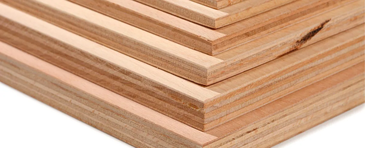
A core gap is a discontinuity within a layer. An overlap places material over another piece and can affect local geometry. Delamination is separation at an interface. These observations should not be combined into one label because the investigation and potential load-transfer effects differ.
An exposed edge can reveal a local issue without establishing its extent inside the sheet. Conversely, a clean edge does not prove that every interior interface is sound. Further examination needs a defined coverage and a way to connect findings to the observed location.
EN 314-2 addresses bonding requirements. Appearance inspection alone cannot replace the applicable bond assessment. Equally, a bond result from elsewhere in a sheet does not automatically determine the consequence of a particular local discontinuity.
Record shape, moisture history and restraint
Bow or twist describes geometry; it is not a direct measurement of elastic modulus. Record whether the panel was measured freely, stacked under weight or restrained in an assembly. Pulling a curved panel flat changes its initial state and may influence the component response.
Ask when the observation appeared: at receiving, after acclimatisation, after machining or during service. Keep storage and wetting information with the inspection record. This timeline helps distinguish the original construction from handling, machining or service changes.
Our moisture inspection guide explains measurement conditions, and the camber and prestress guide explains initial shape versus incremental movement.
Choose inspection coverage that answers the concern
Visual inspection, sounding or an instrument survey may help identify areas requiring closer assessment. Record the method, test paths, settings and limitations. An indication is evidence about the measured response; it is not automatically a quantified void size or a residual load rating.
If a sampled section is needed, preserve its location and orientation. Compare the section with the original indication rather than treating an unrelated cut as confirmation. Use our non-destructive testing guide to distinguish screening, local probing and destructive confirmation.
Define how much of the material was examined. A scan along one path leaves other regions unexamined, and repeated measurements on the same path do not increase spatial coverage.
Compare specimens without hiding the defect position
For an investigation involving bending tests, map the feature before cutting specimens. Keep the direction, dimensions, conditioning, span and loading arrangement consistent with the comparison question. Record whether the feature lies within the measured region and where failure actually starts.
EN 310 provides a panel bending-test method. Identify the method used and distinguish standard-compliant results from exploratory tests with deliberately changed geometry.
Retain individual results, panel identities and failure observations. Compare appropriate reference material from the same defined population where possible. Removing the observed area during specimen preparation can defeat the investigation, while deliberately selecting only extreme defects cannot describe the frequency of defects across the whole lot.
Use the finding to agree the next panel decision
Assess the affected material against the agreed specification and intended application. Cosmetic acceptance, suitability after permitted cutting and structural suitability are separate decisions. For a loaded component, the responsible designer needs the relevant location and performance evidence to assess its use.
Start with the panel photographs and part layout through our contact form. Add the order reference and when the observation appeared if you have them. We can discuss the panel construction, inspection record and sample requirements for the next supply decision. The batch quality-management guide explains how that information supports investigation and corrective action.
Practical buying questions
Which photos help start a panel discussion?
Send a whole-panel view, a close-up with scale and the part layout. Show the feature's position relative to cut edges, supports and fixings so the observation has a useful context.
How can a sample support repeat-order acceptance?
Keep a labelled sample showing the agreed face and edge condition, together with the written acceptance criteria. Include machining details that expose the core in the finished part.